Beam Spring Round 2 (Classic Style) Manual
Looking for the Model F manual? Click here.
Looking for the Round 1 Compact Style Beam Spring manual? Click here.
1. Getting Started
Please review most of the important content, disclosures, and safety information in Action Step 1 of the Model F setup “The Deal” and “Key Rules”
To summarize and offer additional context to the above information:
⚠️ The keyboard does not come fully assembled. Setup and tools (not included) are required. Part of the setup involves opening up the keyboard to reseat flyplates and make other adjustments, as it is almost guaranteed that some flyplates will separate while these keyboards experience rough handling during shipping. Your keyboard is not broken or defective because many keys do not work when it arrives. The keyboard is expected to be delivered in a non-working condition. Adjusting the keyboard is considered part of the setup; it is not considered a repair operation. Additionally, it is expected that ongoing adjustments may be needed to keep the keyboard in operational condition. Do not think that you’ll finish the setup and never have to open up the keyboard ever again. It should take you about an hour or two if you follow the manual, and several weeks if you don’t 🙂
⚠️ Do not skip the manual and then email me or post on the forums asking for help. You need to follow the manual to learn how to do this yourself. In an extremely rare case that the manual does not explain how to resolve an issue, the last step is to email me. Do not post on the forums asking what to do about something. The manual is considered comprehensive; you should not be following any other advice or following how things are done with IBM beam spring keyboards, which are not the same as these reproductions.
⚠️ Safety precautions: Always consult the booklet included with your new keyboard for safety precautions and other important information, including the warning that the keyboard has sharp edges which may cut the skin. Severe harm or even death can occur with any product if safety precautions are not followed. Only use the USB cable that came with the keyboard, as not all USB cables are compatible or safe, especially the “smart,” Apple, or “E-Marked” USB-C cables.
Inspect what you received. Do this within a few days after your keyboard is delivered. Make sure you received everything you ordered and that nothing is broken.
1.1 Downloads & Tools
Needed tools (not included): Torx T8 screwdriver, key cap puller, computer. Possibly needed: soldering iron, pliers, 3mm flat metal file set (to improve the spacebar if needed). Those $12 soldering iron kits from eBay or Amazon will do just fine. Same with the $10 to $15 screwdriver sets with dozens of bits including Torx (better to buy one of these sets than one screwdriver, for all your future uses). The 3mm files can be found for around $8 on eBay.
Required downloads (B104 and B122):
Leyden Jar diagnostic tool (required for setup; see the right side of the page under “releases” to download the precompiled Windows exe, or compile yourself)
Leyden Jar firmware (the keyboard will have firmware flashed to it, but there may be bugs or feature enhancements requiring updated firmware)
Required downloads (BSSK and B62):
1.2 Parts Identification
What do I call each part? How does a Beam Spring key module work?
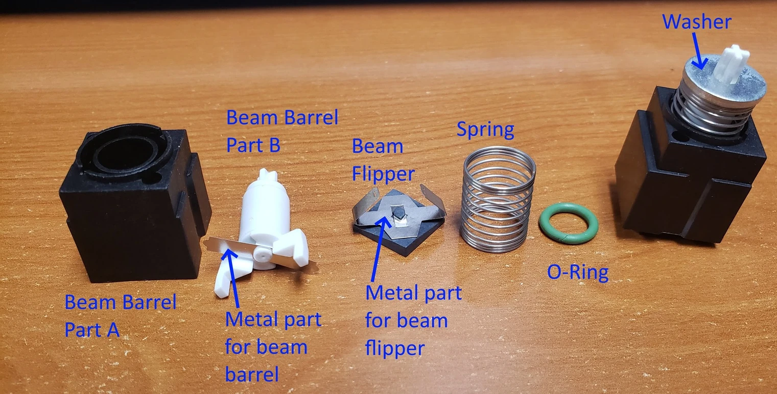
Here are the parts of the beam spring module: beam barrel part A, beam barrel part B, metal part for the beam barrel, metal part for the beam flipper (the “flyplate”), flipper, spring, o-ring, and the press-fit washer. Note that the press fit washers and o-rings are now black in color. The press fit washers have a top and bottom side, as shown in the below video; be careful when reassembling. The bottom side of the press-fit washer has the hollowed-out area.
1.3 Module Assembly
How do I assemble and disassemble a beam spring module? (Very Important!)
The below video is extremely important to learn how to do this; you can’t setup your keyboard without this step. Watch this video several times until you have memorized it! Once more, the keyboard will arrive to you with modules that require adjustment as part of the normal setup process. Your keyboard will for sure not be delivered to you with every module functioning properly. The beam spring mechanism works by lifting up the capacitive flipper when the key is pressed – this is the opposite of how the Model F keyboard works. In the Model F, the flipper is pressed down when a key is pressed. What may not be clear is that there are two notches on the metal part for beam barrel and two corresponding holes on the metal part for beam flipper (interchangeably noted as the “flyplate”); these parts must be aligned for proper operation.
With the round 1 keyboards you had the option to manually bend parts of the flyplate to adjust sound and functionality. With the round 2 keyboards, this step is not needed or even possible; the metal and annealing processes have been updated so that the flyplate stays perfectly in place; do not try to bend it. It’s okay if it flexes a tiny amount while you attach the metal part for beam barrel. To accommodate MX-style plate mount stabilizer inserts, the beam spring module housing (beam barrel part A) of the space bar have been trimmed a bit, so if you need to replace this key, keep the original beam barrel part A. The trimming has no effect on keyboard operation but they do not allow the key to “lock in” to the top of the case like all the other keys.
🎬 Video — Beam Spring Module Disassembly & How It Works
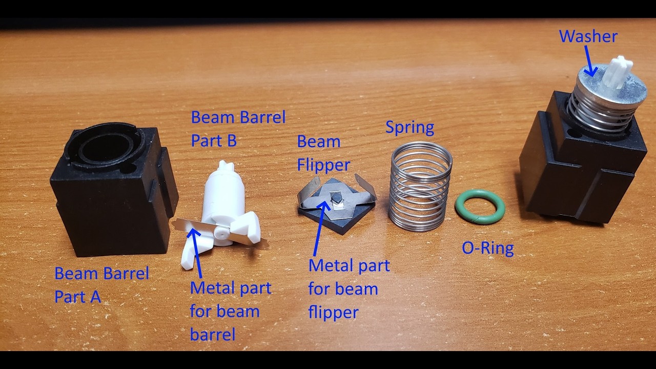
Understanding the mechanism: how to correctly assemble and disassemble the module, align the notches, and handle the flyplate.
You may notice that stabilizers are neither included nor recommended, except for the spacebar, though they may be purchased separately. For all the keys except the space bar, these stabilizer inserts actually hinder operation of the keys and will make them get stuck in almost every instance, so they are neither recommended nor included. You should only use the space bar’s stabilizer insert and leave all others uninstalled. With the beam spring module design, even the widest Right Shift key functions fine and can be pressed even in the extreme corners without the stabilizers. However, some folks disagree and find performance to be better with stabilizers. Other plate mount stabilizers may not work since the beam modules are thicker and require stabilizers with a metal wire that is far enough away from the module. I recommend ordering spare stabilizers that exactly match my photos (I currently offer them here).
2. Key Module Testing & Firmware
2.1 Flashing Firmware
First up, we will check for firmware updates: https://github.com/mymakercorner/vial-qmk/releases
I’m flashing the 6/8/26 firmware as of now; it fixed some bugs and enhanced reliability. You should update if your OS’s devices window notes an older date noted in the keyboard’s name.
The B104 and B122 keyboards use the RP2040-based Leyden Jar, which is very easy to flash. Just download the Leyden Jar Diagnostic Tool and extract the contents to a folder. Launch the program. Connect the keyboard. Click refresh. Make sure the beam spring keyboard is selected in the top left area that now appears. Click Enter Bootloader. Then copy and paste the file to the empty drive letter that appears in your explorer program, with the drive name “RPI-RP2.” It’s best to unplug the keyboard, wait several seconds, and plug it back in (if doing diagnostics in the Leyden Jar diagnostic utility, remember always to click refresh after plugging a Leyden Jar keyboard back in, as the program does not auto-refresh). That’s it! Usually you can also just press Fn+Spacebar+R on your B104/B122 to enter the bootloader, but this method may be less reliable. On rare occasions the keyboard may not boot; in these cases check if you are seeing the RPI-RP2 drive (indicating you need to reflash the uf2 firmware) or you need to physically short the controller’s prog pins when plugging in the keyboard (it may take several tries to get the timing correct) which will put the drive in bootloader mode so you can flash the firmware again. Refer to Model F Action Step 8 for more details on shorting and troubleshooting.
The BSSK and B62 keyboards use the xwhatsit controllers, so you can’t follow the above flashing process or Leyden Jar Level Monitor for them. Instead, follow the firmware flashing steps in the Model F Action Step 10 and the pandrew Signal Level Monitor testing steps in the Model F Action Step 7.
The below video for Leyden Jar keyboards (B104 and B122) shows the steps to flash the latest firmware and test each key. If you’re on the latest firmware, you can skip the firmware flashing part at the beginning of the video. After flashing, unplug and plug back in the keyboard. Click refresh device list, Level Monitor.
🎬 Video — Key Testing and Firmware Adjustments
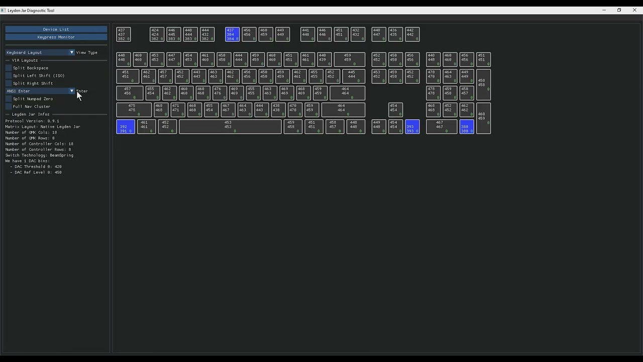
Flashing the Leyden Jar controller, refreshing the device list, and running the initial Level Monitor diagnostic test.
2.2 Testing Keys & Adjustments
For all Round 2 beam spring keyboards:
Plug in the keyboard. If it is not detected, try another USB port, or disconnect and reconnect the USB-C plug that connects to the controller (unscrew the 4 case screws as shown later in this manual, then return to this point), as the connection may have loosened in shipping. First, visually confirm that each press-fit washer is pressed down all the way, so that the white part of each module has the same visible height. If one white cross part looks smaller, it means the press-fit washer may not be pressed down all the way. Gently use two thumbs, one on each side, to press down the washer until it is even with the height of the others. With the above program’s signal level monitor clicked and open, you are now going to press and hold each key for 2-3 seconds, until a third number registers for each key. The 3 numbers for each key module are the low, current, and high values. Remember that a pressed beam spring key reduces the capacitive signal as the flipper is lifted up when the key is pressed, so the “pressed” key signal value will be lower than the unpressed keys.
Sometimes, when initially pressing a key a few times after it is transported or bumped around, it will not register or click strongly, and pressing maybe 10-20 more times with different levels of force will get the key working, while other times the keyboard needs to be opened to adjust the module. Sometimes the metal parts are not separated but the module still does not click (it was probably bumped out of alignment due to drops sustained in shipping): use your thumb and pointer finger on the press-fit washer and top white cross part to press as down as it will go with a little force while angling it as leftmost and then as rightmost as possible (but not using so much force as to break it!); this often causes the module to start working again after several tries. If this doesn’t work, follow the normal process to disassemble the module while the inner assembly is open, as described later on. As you use the keyboard in its initial months, it is expected that some previously working keys will stop working, for example when a key needing adjustment was not discovered as needing attention in the initial setup. This is why these keyboards are considered great for typing but not for gaming or other mission-critical work.
You can see right away that 3 keys need adjustment, since they are being registered as pressed. What often happens during shipping is that the flyplates separate from the rest of the module, so they are not evenly resting on top of the large capacitive PCB underneath each key. That makes their pads register with a lower signal value since the capacitive flipper is not resting on the pad as it would normally be. However sometimes they will rest evenly and still not function, so don’t assume that only these 3 keys need attention. That is why we are physically testing each key. You will notice that the video has been shortened for time, which is why suddenly many keys will be registered all of a sudden. To save time, I sometimes test a few keys at a time, so multiple blue keys would register as pressed at the same time. And finally towards the end of the video I change the View Type to QMK matrix, which may help diagnose issues where an entire matrix row or column does not work (if the ribbon cable needs resoldering, for example). In this example, R7 and C17 are unused, and several other matrix positions do not have key modules populated (for example, the 5 hidden keys above the cursor keys), so they will appear pressed all the time. And the last part of the video shows how you can temporarily adjust the layout to expose different pads, such as split keys; these splits are not saved into the keyboard memory (you’d have to use Vial for any adjustments that you want saved).
Take extra time to test pressing the spacebar from various angles and positions and with varying amounts of force, so that it never gets stuck or is slow to return to its full upright position. As detailed in the spacebar section, some looseness and movement is by design and considered normal, but it should not get stuck. I test every keyboard’s spacebar to make sure it is good, but you may find that some spacebars get stuck or are exceedingly hard to press. By design the spacebars should be a little harder to press than the non-stabilized keys. You should not need to do the following, but it is included in the manual for sake of completeness: what I do in these situations of a spacebar that is not good is (after the inner assembly is opened and bolted as shown later on) add 1 or 2 of the spare springs below the spacebar for extra support, as detailed in the next paragraph. If that doesn’t work, increase the amount of the spring that is above the TIA plate. Then replace the beam module itself. If that doesn’t work, I use a 3mm metal file (just do an eBay search for 3mm metal file set) to file two areas of the inner assembly stabilizer cutout: the bottom edge and the upper side of the outer edge, as shown below. Only file 0.5 to 1mm. Filing too much will make the spacebar excessively wobbly; a small amount of wobble is required as a compromise to adapt the slight looseness of beam spring module design to today’s MX key design. Better to file less and test (you have to close up the inner assembly fully and flip it over (see below instructions) to test the spacebar. The MX stabilizer should have a little movement by hand when it is installed in the inner assembly plate; test for this while filing. The top part of the below image shows what the spacebar looks like while it is upside down, and the bottom part indicates in cyan color which areas should be filed. As always, follow proper health safety protocols for filing aluminum, including protecting eyes and respiratory protection (file outdoors or with a proper mask, etc.).
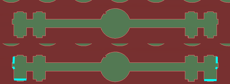
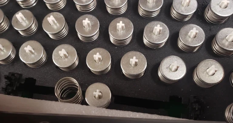
Needed for Round 1 only, but you may want it for Round 2 if you prefer a heavier spacebar or the spacebar is not returning after it is pressed: We are going to insert the spare beam spring into the spacebar area shown and twist the spring a few times either clockwise or counterclockwise as needed. The more the spring is visible on top of the keyboard, the more force the spring will require to press it. I like 5 spaced out “rings” or turns of the spring to be visible, plus the 3 rings pressed together at the ends of each spring, so a total of about 8 rings. This gives the space bar a slightly heavier weighting than the other keys while reducing the chances that the force is not enough to have the spring return after it is pressed. If you prefer a lighter spacebar force, you can twist that spring so less of it is visible outside the keyboard, though as mentioned before if you do too little then the spacebar may not operate properly. After installing the spare spring or springs, attach the spacebar only to the beam module; do not press down on the MX stabilizer inserts. If the spacebar appears rotated so that one side is closer to the row of keys above the spacebar, then gently rotate the spacebar in the opposite direction. It may take a few tries before the spacebar is no longer significantly rotated. Please do let me know if you do any experimentation with the spacebar and have any recommendations.
Write down which keys do not register.
2.3 Using Vial to Adjust Keys
Next, you can use Vial to adjust your keys or view how the keys are currently mapped. Vial is a free, open-source GUI that allows instant adjustments to your keyboard without the need to flash firmware. Just go to Vial.Rocks in a chromium-based browser, or download the program for offline use. A handy feature for the Leyden Jar controller is that the keyboard name will have the date of the firmware, so you’ll always know which firmware you’re running (hover your mouse over the keyboard name in the Leyden Jar utility to see its full name, since the date is at the end of the keyboard name). You can also see this in your operating system’s device manager. In the below video example, the top left key that was normally set to Esc is set to F1 as a test, just to show you how to change the key, and then it is changed back to Esc. The video shows double clicking a key to enter MO(1). This is a special key called the Function layer key. You press and hold the key to use keys in your second layer (named Layer 1, since Layer 0 is the base layer), such as the media keys shown in the video. Press Fn+Spacebar+ other keys to enter the bootloader or other keys as shown in Layer 2 in Vial.
🎬 Video — Using Vial to Adjust Keys
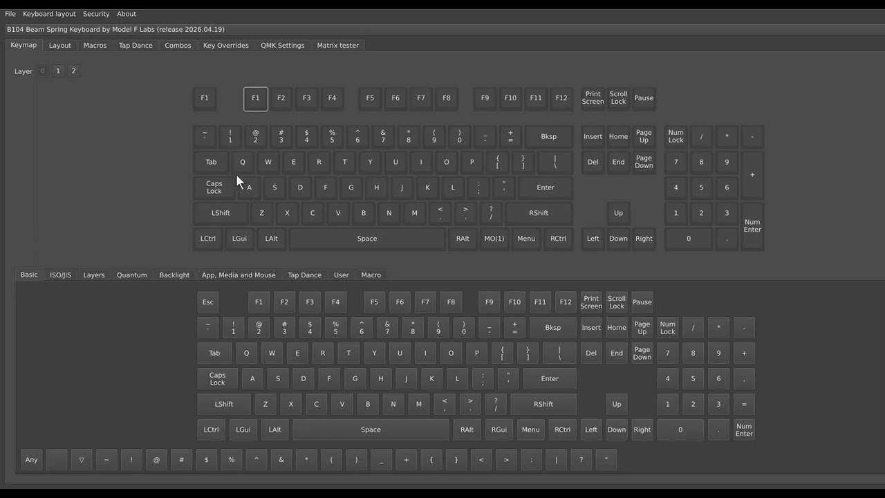
Vial configuration: checking mapped keys, altering key bindings (like setting Esc to F1), and verifying Function (MO1) layer commands.
The video shows what working and non-working beam modules sound like. Notice how I am now testing by pressing each module several times and quickly, and at different angles and amounts of force. This is a recommended test that is separate from the Level Monitor test noted above. Remember that pressing a key fast will not register in the signal level monitor, which takes a second or two to register, so don’t think the key is broken. Sometimes this may catch a module that is slightly misaligned. The more you test, the less you’ll have to take apart the keyboard later if a module works fine now but later fails. You can see that two of the keys identified earlier (Left Ctrl, Right Cursor Arrow) make sounds but do not make any click sound when pressed even if they weakly actuate enough for the key to be registered in the Level Monitor, and the Num Pad Period gets stuck and doesn’t move back up freely. If a key buzzes, it is often the spring; just rotate the module’s spring and press the key a few more times.
Write down which keys do not make a click sound.
🎬 Video — Key Testing
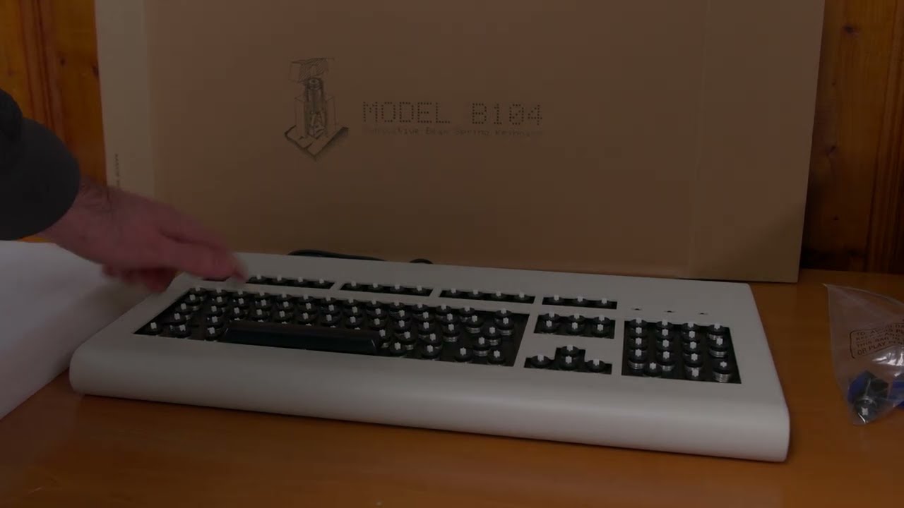
Keypress diagnosis: hearing the difference between a working module click and a misaligned module, identifying stuck keys, and resolving spring buzz.
3. Opening the Case & Inner Assembly
The beam spring keyboard is far easier to open up compared to a Model F, whose plates are slid together and held together by sliding tabs. These Beam Spring keyboards can be opened up easily with just a Torx T8 screwdriver. Remember to put the keyboard on top of the foam inserts so as to protect the case. You can see me bolting in the inner assembly attached upside down to the bottom case, so that it does not slip and fall (then all of the modules would fall out and you would have to manually insert each one again!).
3.1 Case Access & Tabs
If all modules work perfectly and the spacebar is already installed, you do not need to open up the keyboard unless some issue comes up in the future (for example, a module stops working reliably). You can skip the remainder of this step if applicable, but keep in mind that over the first month or two of your full-time keyboard usage, you may need to reopen the keyboard or use an air blower if debris is preventing normal operation of some keys, especially if you do not notice damage to the most fragile part of the keyboard, the white “Part B” which may be partially cracked and then may break off completely at some point, and then after that it would take a little time for debris to make the keyboard not usable or you would notice that a key seems to wobble a lot (for example, if one of the Part B “legs” has broken off). Every time a beam spring keyboard is moved, especially during today’s relatively rougher shipping, there is a risk of damage, just like with the IBM originals – after I received them, I had to replace several of the modules. Remember that these issues are covered per the limited warranty and I have plenty of Part B spares (just email me with documentation of the steps you want through along with photos of the damaged parts). Additionally, I have made extra complete modules which can be ordered individually or through the deluxe first aid kits which are just bundles of 12 modules. You’ll be using this keyboard hopefully for life, long after the limited warranty is done and after the project has shut down, which is why I strongly recommend getting all the recommended spare parts with your keyboard order or within a month or so after that.
Rarely, the amount of shipping g-force will be so high that some of the four tabs connecting the top and bottom case will be bent, which results in the inner assembly not being properly aligned with the case. This is a quick fix when you have removed the 4 bolts of the top case that connect to these tabs: just use your pliers, protected with rubber or many thick layers of tape so as not to chip the paint, to bend them back in place. See the below image for reference on how the tabs should be positioned. Basically they should be parallel to the bottom of the case and perpendicular to the two sides of the case. As mentioned many times in the manual, these kinds of adjustments are considered part of the required setup for all keyboards instead of a defect requiring a return.
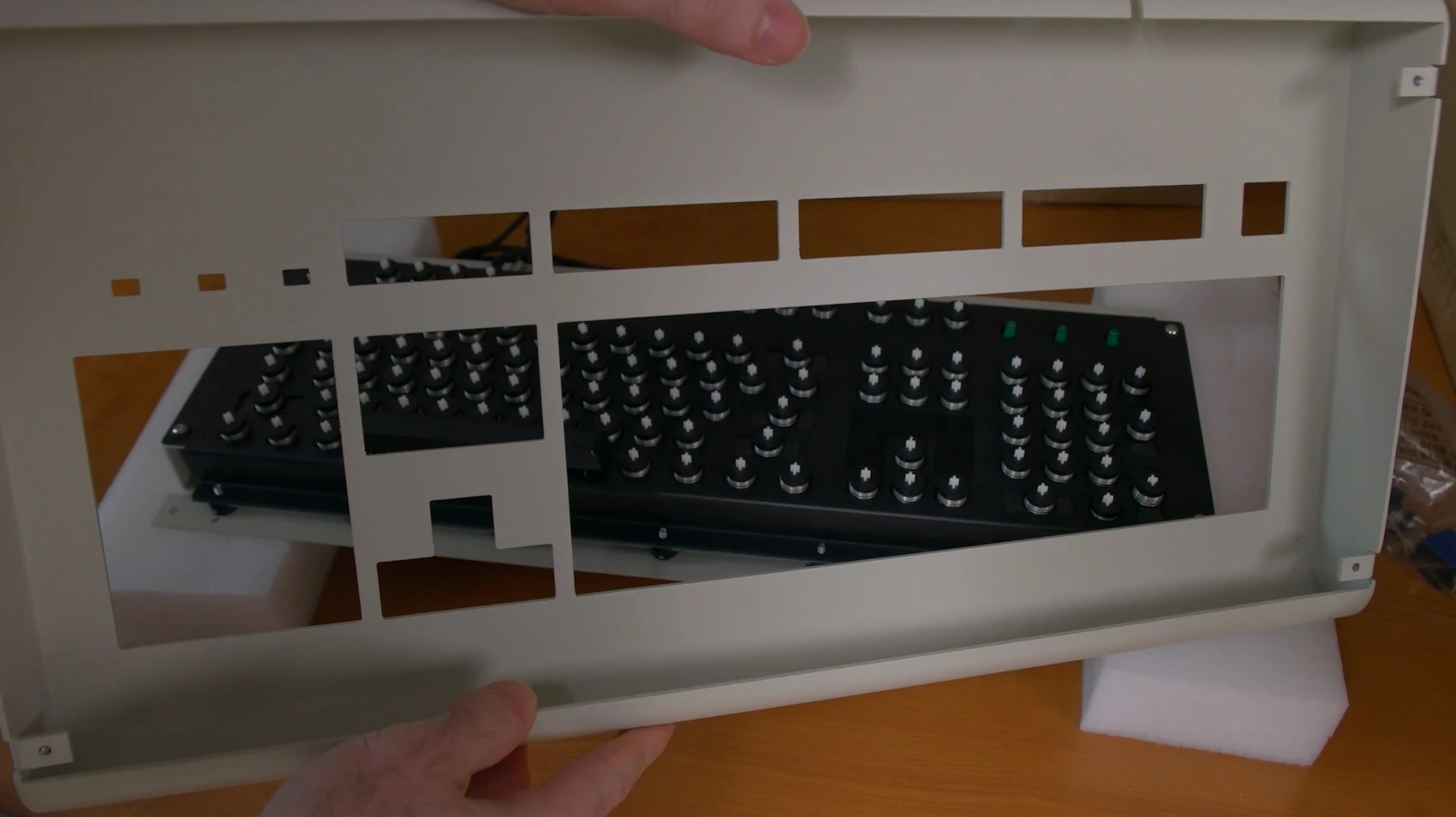
You’ll notice that the bolts on the bottom inner assembly are protected by plastic caps, which serve to protect the paint finish as well as to reduce the flex of the bottom case when pressed inwards. The bolts towards the top row of keys also have metal cylinders for this purpose; be sure to reinstall the same way. These metal caps cover the holes for the threaded bumpers near the bottom row of keys; if you are using a bumper with a bolt like the 1/2″ and 1″ bumpers, be sure to remove the two caps covering those holes and reattach the bolts without the caps, which were not really needed for those positions. Don’t forget to reinstall the 2 cylinders for the controller; if the controller is not firmly grounded then you’ll see key spamming, keys outputted out of order or swapped when typing fast, and other issues.
Be sure to avoid flexing the gray ribbon cable unnecessarily, as that will weaken the connection and cause issues. If you have to flex the cable, do so in the middle of the ribbon cable where it is already bent, not at the edges, though you’ll need to do a tiny amount of bending if you need to separate the PCB from the gold bottom inner assembly plate.
3.2 Cleaning & Inspection
Inside the keyboard you can see that there is a foam piece with cutouts for each module hole. It is placed between the top inner assembly (the black metal plate inside the keyboard) and the tops of the modules. You can also see there is a thin foam between the PCB and bottom inner assembly (gold color plate) for some sound reduction and insulation.
Inspect and clean the large capacitive PCB for debris and liquids/oil. Oil is transparent and difficult to see, so it is best to wipe the PCB top thoroughly with a dry, lint-free cloth, being careful not to damage the LEDs or controller wiring, even if you don’t see any visible liquid or debris. If you don’t do this, you may notice some keys not emitting their signal reliably when pressed, double pressed keys, or other issues. The bottom does not need wiping. If you’re in a dusty room you may want to quickly wipe it once more just before you close everything up. It is best to keep dust out of the beam spring modules by covering the keyboard with a dust cover when not in use. As with the IBM originals, dust affects the capacitive sensing, so you may need to occasionally open up the keyboard inner assembly and use a microfiber / lint-free cloth to wipe the large capacitive PCB as well as wipe any flippers with visible dust. Do not use an air blower as you may blow modules out of place by accident. A big clump of dust may cause a key not to actuate reliably, or be recorded as pressed when the keyboard is first plugged in, resulting in the key being outputted continuously.
After that, check each of the bottoms of the flippers for debris and oil. Do not remove the modules; just carefully clean them in place by hand, only if you notice debris or oil; do not touch every one unnecessarily. Never use compressed air or a blower/fan/hair dryer. Do not be careless; you could knock some modules out of place; they are not secured to the top inner assembly.
🎬 Video — Opening the Case & Inner Assembly
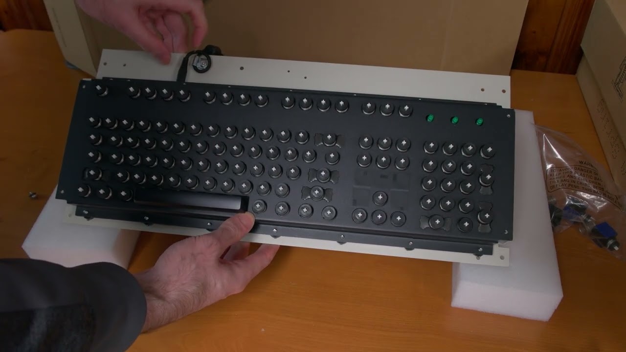
Disassembly walk-through: unscrewing the Torx T8 bolts, flipping the inner assembly safely to prevent modules falling out, and inspecting the PCB.
4. Module Adjustments & Flyplate Reattachment
As setup continues, we are now ready to adjust those modules whose parts were moved out of place during the drops and high G-forces sustained while in transit. Remember that back in the day IBM would have these computer systems delicately loaded onto a company truck for direct delivery to the clients who needed room-sized mainframe systems to which terminals and their beam spring keyboards connected. They didn’t go through the mail. There was obviously a reason for this: they didn’t want all their equipment destroyed by the common mail carriers; rough carrier shipping was a problem even decades ago! Since I can’t hand deliver these all around the world (!) the only alternative is for the keyboard to be delivered in a non-working state and to require these setup steps to be done as a required part of the setup. This has always been the way of these IBM reproduction keyboard projects, going back to their start in 2016.
4.1 Flyplate Reattachment
The decision to go with a press-fit washer has made flyplate reattachment far easier than with IBM’s beam spring module design, which required taping the module and then using a paper clip to carefully move the thin metal back into place. Now you can quickly take apart the module by hand to reattach the flyplate in minutes. The only tricky part is to make sure the two metal parts connect to each other.
Another good thing about the beam spring design is that you don’t have to remove all the keys to adjust a module or open up the keyboard in the future. If a module needs adjustment, just remove the affected key’s keycap; then you can follow all the other steps to remove the affected module for adjustment or replacement.
Flyplate reattachment to the flipper: Occasionally you may see that the flyplate has separated from its flipper. You can see in the flyplate photo below how it should be attached, though it may be easier to reference one of the spare modules that you received. The flipper is sloped on two sides; the “wings” of the flyplate should go where those sloped sides are. Just carefully center the flipper and use your fingernails to push it back in place. This is a little tricky and sometimes it takes a few tries. Sometimes it’s best to remove the flyplate and push downwards on those two little folded parts in the center that attach to the flipper, and then try again to reattach the flyplate and flipper.
When putting the press fit washer back on the module, it is important that the module is pressed all the way down with a minimal amount of force; not so much force that you break one of the plastic legs of that white part inside the beam module.
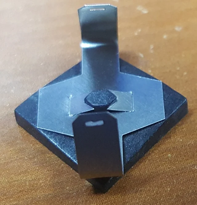
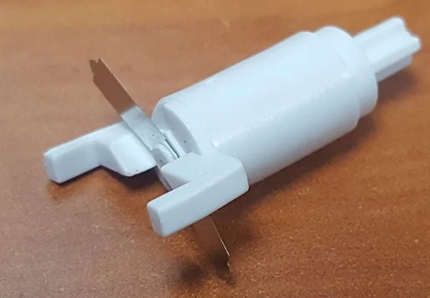
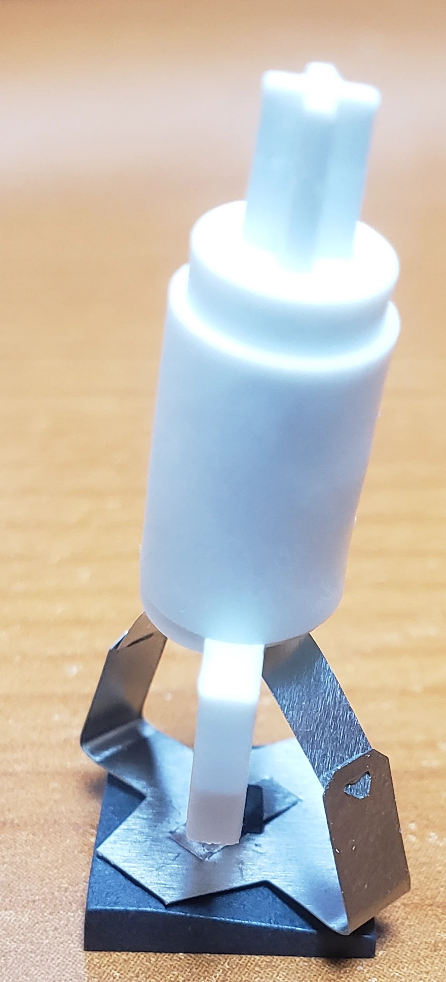
Reference imagery for flyplate alignment, flipper reattachment, and the full module stack up.
Broken white “leg” on the beam barrel part B: you may notice a broken off white part when removing a module for adjustment. Sometimes this is hinted at when you can’t press a module down all the way. A partially broken leg should not be repaired; just discard the white part only; do not throw out the entire module. As noted on the product pages, when I send replacement parts, I only send this white part with its attached metal part, unless some other part of the module is broken as well; I do not send complete assembled modules as replacements. Complete modules are only available individually and as part of the first aid kits.
Each beam spring hole in the top inner assembly (the black plate) is tabbed to correspond to a notch in the module, so be sure to position things correctly when putting everything back into position. The notch should line up with the hole in the module. For reference you can see how your other modules are installed. The vertical keys have their beam spring modules rotated, so keep that in mind. The module may break if you do not pay attention to proper orientation of the module to fit the slot of the module and the notch of the top inner assembly. As a note the keyboard may now be reversed from left to right, so keep that in mind when determining which modules to remove.
Optional steps: now is the time to file the spacebar stabilizer area of the top inner assembly plate if more looseness is desired (see the earlier Step 2 for more details). Again, I do this for you if needed as part of my QC, but you may need or want to do this. My advice is not to touch it unless the spacebar is getting stuck or is slow to return. Another optional step would be to leave the bottom bolts uncapped, with the attached caps not sticking outside the perimeter of the bottom inner assembly plate. You may have noticed that the bottom case is slightly lower than the top case and sticks out a little. This was by design, to reduce case flex, but you may prefer additional case flex and a more uniform case appearance.
For a more clear understanding of module disassembly and reassembly, refer to the videos in Action Step 1 once again, in addition to the videos.
🎬 Video — Flyplate Reattachment
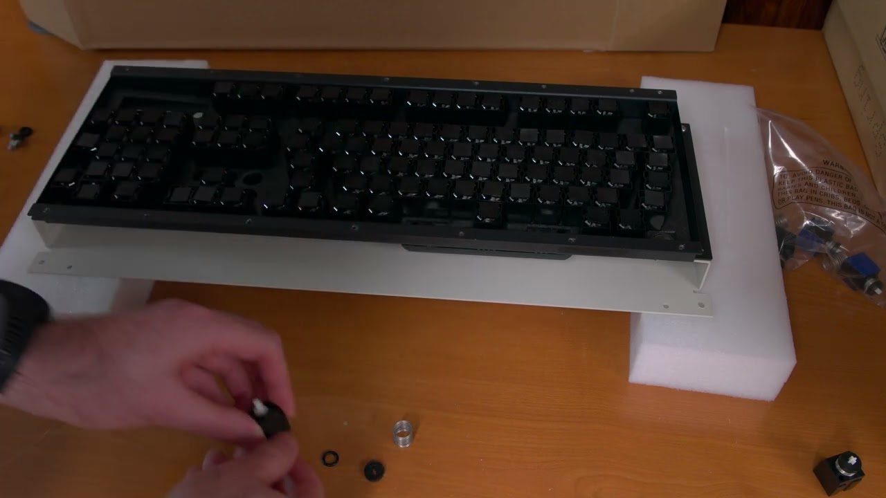
Demonstration of pressing the press-fit washer, sliding the flyplate wings onto the flipper, and snapping everything together.
4.2 The Wiggle Method
The wiggle method: Most of the time, the only needed adjustment is to reattach the flyplate. Occasionally due to variations in tolerances between the size of the hole of the beam module part A and the diameter of beam module part B’s cylinder, they may get stuck. The way to fix this is by using the wiggle method (or if you have spare modules and want to save time, just replace the module but save this original module for later).
The wiggle method consists of three levels, shown in order in the below video:
- The first one to try is just the circular wiggling. You may want to do this a few times, testing as you go.
- If that doesn’t work, the video then shows how to widen the beam module part A (the black part) if the module walls are causing too much friction with the legs of the beam module part A (the black part).
- And finally if needed, pliers to the rescue! Use your pliers (protected with electrical tape or rubber to avoid marks) and a small amount of force in a back and forth motion, then rotate the module 90 degrees and go again back and forth, to widen things as shown. Grip the cylinder, not the very top of the module where the cross is; otherwise that cross will break right off. The example shown was a more extreme example where all three of these steps were needed. It should be widened with the module in both the pressed position as well as the nonpressed position.
Even with all three of these methods, you should not spend more than a few minutes adjusting a key. By no means should you be spending hours on any one operation. Again, if this is too much for you, you can just use one of your spare modules. The wiggle method can also be performed with the module installed in the keyboard, if you notice a key getting stuck during its initial months of usage and did not catch this during setup. Usually pliers would be needed to fix it successfully while it is installed.
🎬 Video — Wiggle Method
Walking through the 3-step wiggle progression to reduce friction inside a tight beam spring module housing.
See the below video on removing the tape from one of the spare modules, so as not to break anything or separate the flyplate. Make sure one finger is pressing the flipper as you pull off the tape.
🎬 Video — Remove Tape from Spare Module
How to safely remove the holding tape from a spare module without accidentally separating the flyplate.
5. Spacebar Installation & Removal
If you bought a keyset as part of your keyboard order, the spacebar should be preinstalled for you and these steps are not needed unless the spacebar requires adjustment, but this section is still important to read so that you don’t break something later. There are two methods for installing the spacebar: the preferred method (must be done when the bottom inner assembly plate is removed, as it is now if you’re following this manual) and the more risky method if the inner assembly is closed up and the top case is removed (using a Model F or Model M stabilizer wire). For some keyboards the spacebar needs one or two beam module springs below it; this hasn’t been the case for the Round 2 boards as of now but you may need to add these springs in the future (click the Round 1 beam spring toggle button on this page to expand the section, and then do a Ctrl+F search for “heavier spacebar” on this page to see more details). It is expected that there will be some movement or rotation for the spacebar, more so than with Cherry MX type keyboards. This is part of the compromise of this project’s adoption of beam spring modules to MX keycaps.
5.1 Spacebar Installation
The safe way: with the keyboard inner assembly upside down and secured (as per the above steps), first install the spacebar on the beam spring module (the center cross inside the spacebar). Use one hand to press down on the spacebar module to keep it in place, with the other hand pushing the spacebar upwards until it is installed. Then use a finger to press down on the bottom of the plastic stabilizer while at the same time pressing the corresponding spacebar edge (right above where the cross is inside the spacebar) upwards so that it is installed. Then do the same for the opposite edge.
The riskier way: if you do not properly support underneath the plastic stabilizer while pressing down on the spacebar, you will for sure snap the stabilizer and have to purchase a new one. See the video on how to use the Model F stabilizer wire to press firmly underneath the plastic stabilizer to support it while you press down on top of the spacebar, being sure to align the spacebar’s cross with the stabilizer’s cross. At the very end, hold the keyboard horizontally, spacebar end up, and gently press down a little at a time for each of the 3 contact points (the two stabilizers and the beam module itself) until they are all the way down. If they’re not all the way down, you’ll notice that the spacebar is uneven or stuck. As shown below, all you have to do is remove the 4 bolts to remove the top case; you don’t have to disassemble the dozen or so bolts of the inner assembly.
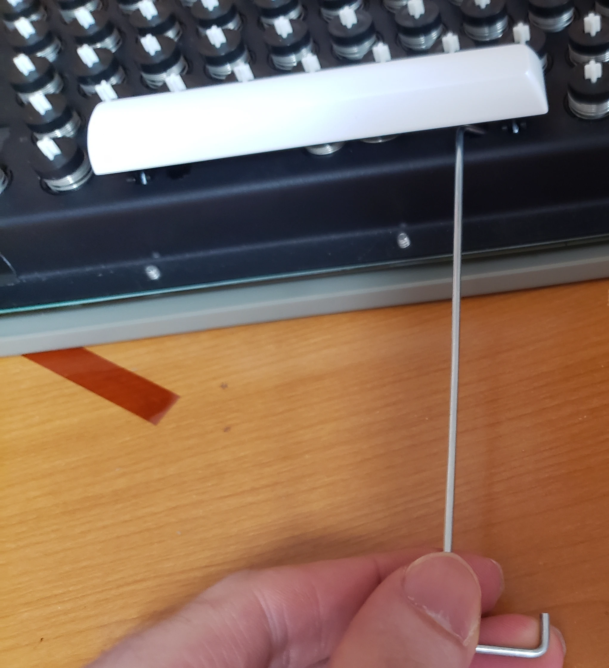
🎬 Video — Spacebar Installation
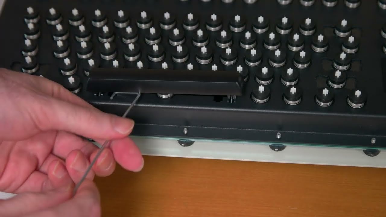
Demonstrating both the safe installation method (inner assembly open) and the riskier wire-support method (inner assembly closed).
5.2 Spacebar Removal
Removing a spacebar is also risky. Be careful not to damage the plastic stabilizers, or buy some extras from the shop! If you use too much force after following my video below, you will break your stabilizer and your spacebar will not work well.
🎬 Video — Spacebar Removal
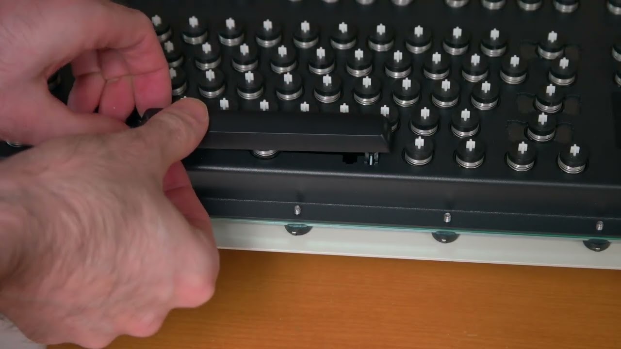
How to safely remove the spacebar without cracking the fragile plastic stabilizers.
6. Keycap Installation & Removal
Be extremely gentle when pressing each key down to install it; you can easily break or fracture the white part of the beam module if you press too hard. If you later notice small loose white pieces inside the keyboard causing some keys not to work, you probably broke some modules’ Part B while pressing hard. You should never press down a key with more force if it is difficult to install. Check that the cross on top of the affected beam module is clean and free of flashing or excess plastic, and then try to install again. When removing keycaps with a key puller, ensure that you are not also removing the washer and spring on the top of each beam module. The “arms” of the key puller should not be too close to the center of the module).
While you are installing the keys, beam modules may also become stuck; lifting up the key with your fingers and then pressing it a few times usually stops the key from becoming stuck again. If that does not work, follow the wiggle method (removing the module from the keyboard is not necessary unless it broke, the flyplate separated, or the key remains stuck), but this time be much more gentle.
My recommendation is to install all transparent relegendable keys (and possibly MX keys from other manufacturers) with a piece of clear/transparent tape, saran wrap, or plumber’s tape between key and module so that you do not have to worry about it falling out. The worst that can happen is that the key won’t be able to be pressed down all the way because the key is already tight – in that instance, just remove the tape and install the key normally (though it’s possible to crack the key – be careful!). Due to the variations of tolerances between key stems and keys, occasionally a key may fit so loosely that it falls off easily. I have not seen this issue at all with the project’s full key set but it may happen with other MX key sets. I have also seen this with the transparent relegendable MX keys being sold with the project since their tolerances do not appear to be as tight. This means that if you purchased these relegendable keys or other manufacturers’ keys, it is possible that some keys will fall off if you hold the keyboard upside down or while typing. There are various safe fixes for this, such as putting a piece of paper or scotch tape between the key cap and the beam spring module’s stem, which you may need to do as you set up this keyboard. These fixes will completely stop any loose keys from falling out. The usual warning applies here that you should not use your favorite (or a valuable) MX set on these beam spring keyboards as there is a chance that it cracks a key. I don’t recall reports of this but you have been warned!
It is expected that there will be some movement or rotation for each keycap (especially the 2U and larger keycaps), more so than with Cherry MX type keyboards. This is part of the compromise of this project’s adoption of beam spring modules to be compatible with MX keycaps. This is in my opinion part of the appeal of beam spring keyboards: they are in many ways true to the feel and experience of their predecessor, the IBM Selectric typewriter; each of those keys was attached to a series of metal parts and had a range of movement.
🎬 Video — Keycap Installation and Removal
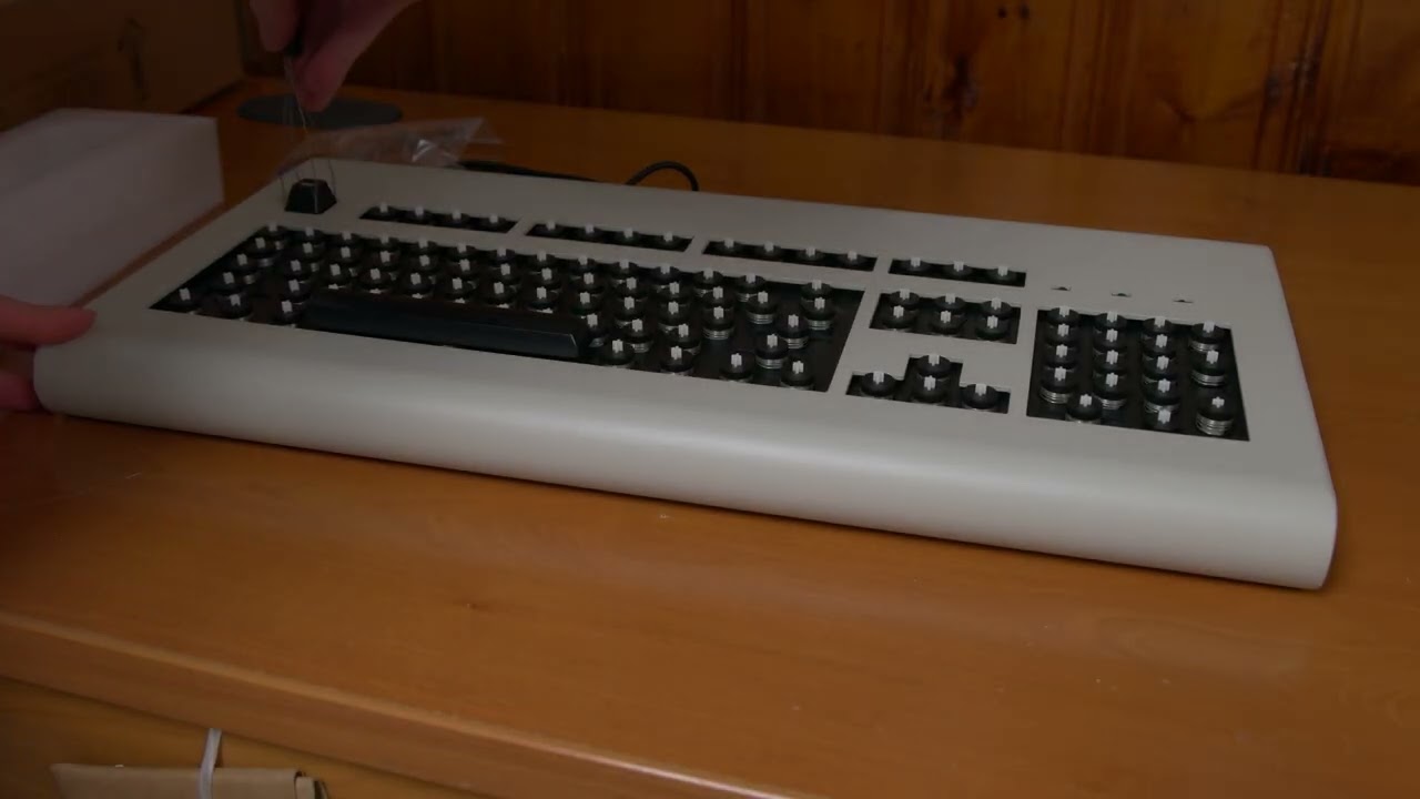
Installing keycaps gently to avoid snapping the cross-stem, and the tape trick for loose keys.
7. Final Steps
Before you proceed, now is the time to install screw-on bumpers (an optional add-on). As noted earlier, if installing screw-on bumpers to the lower two holes, you’ll need to remove the two nearby caps and just screw in the bolt without the cap, since the cap will be in the way of the nut.
After that, install your solenoid driver and solenoid (optional add-ons). To do this, follow the instructions in the Model F solenoid section while paying particular attention to the photo below showing the beam spring case and controller bottom side. The only differences are that you are using two countersunk screws to attach the solenoid to the case bottom and you are attaching the solenoid driver to the bottom case instead of the top case, using the large countersunk screw in your kit. Between the solenoid driver PCB and the case, insert one of the rubber spacers. Install a nut on top of the solenoid driver. With regard to the orientation of the solenoid driver cable (to avoid destroying your solenoid driver), the red wire of the cable should be closest to that top edge (same for both xwhatsit and Leyden Jar). To be safe you can remove the 4 screws of the top inner assembly to better see the controller. Remember that the keyboard and solenoid won’t work until every key module is working, so don’t try to type normally on it (only the signal level monitor will work). That’s a limitation of beam spring tech as the keyboard sends a signal when no contact is made with the flipper, so if even one key is off the keyboard might continuously send that signal to the computer. The Model F “fixed” this and only sends the signal when the flipper is pressed down onto the PCB.
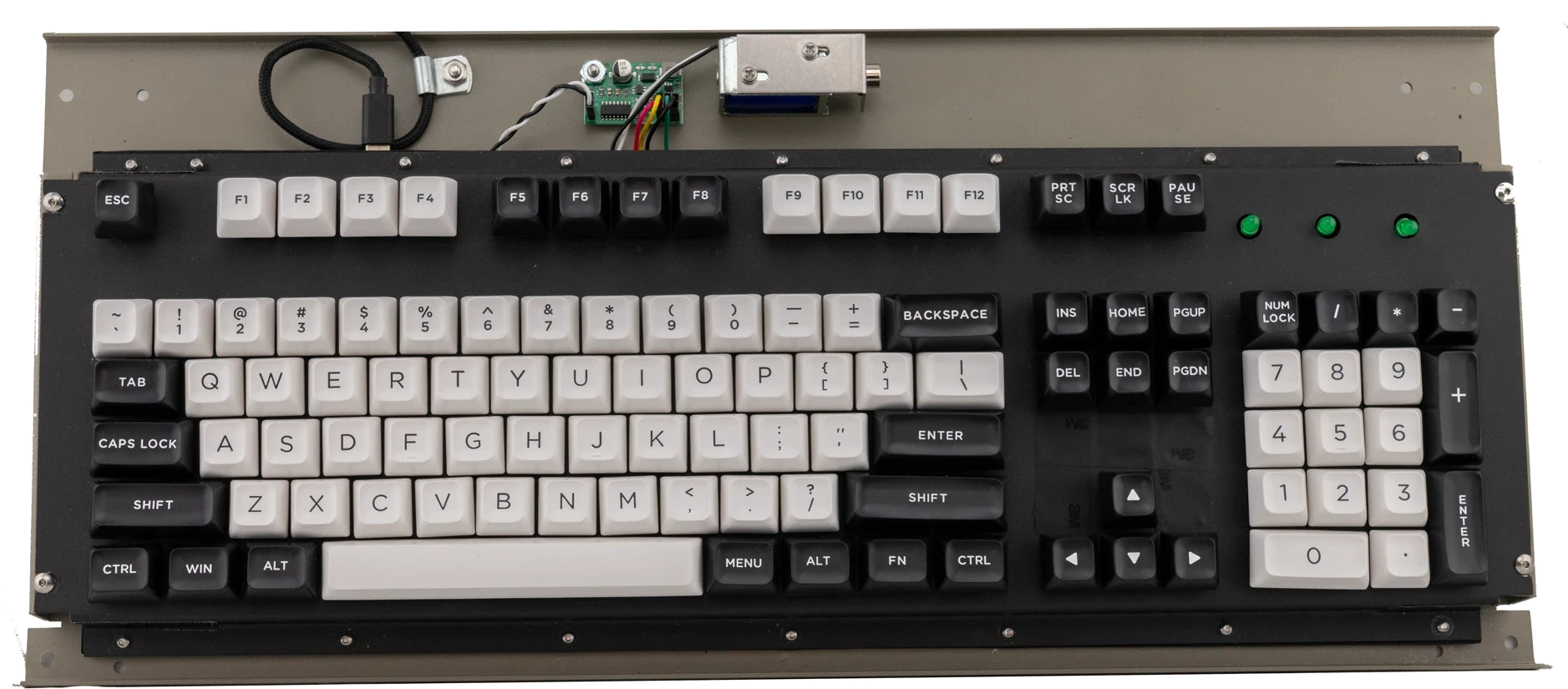
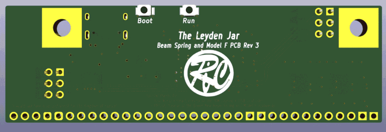
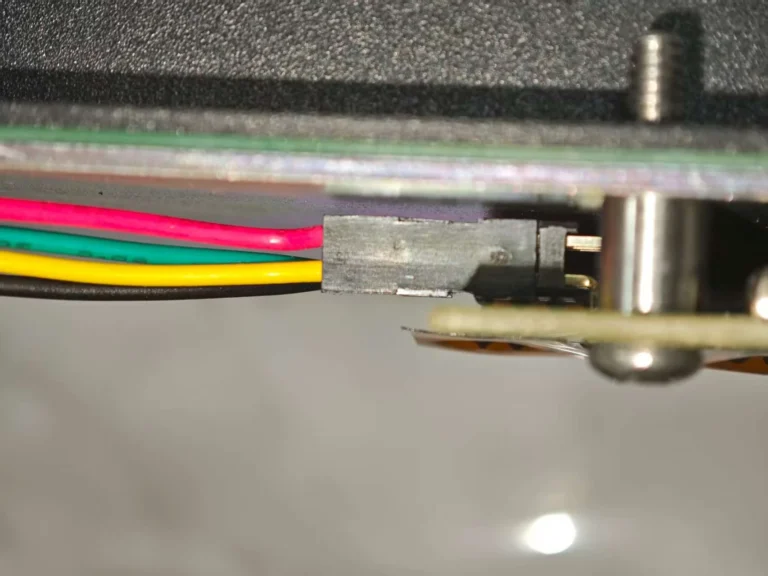
Remember to do one more wipe with a dry, lint-free cloth on the entire PCB surface, make sure that orange polyimide tape does not block any area of the nearby pads, and make sure there is no dust or debris on any of the flippers. Ensure that the holes of the foam between the plate and PCB are aligned with the plate and PCB holes. First put the metal cylinder spacers between the controller and bottom inner assembly plate (each controller bolt goes inside a cylinder).
When putting everything back, do not tighten too much. In our research over the past few years to get these keyboards to be in line with IBM’s standards, we have found that having a slight looseness to the assembly results in a far nicer sound and typing experience. Just back off the tightness a few turns by eyeing it and keep things loose for optimal sound and performance! Stop before you feel that you are using extra force to continue turning the screwdriver. It should not be so tight that the bottom plate bends so it looks slightly curved, but don’t make it too loose that the modules fall out!
🎬 Video — Closing the Inner Assembly
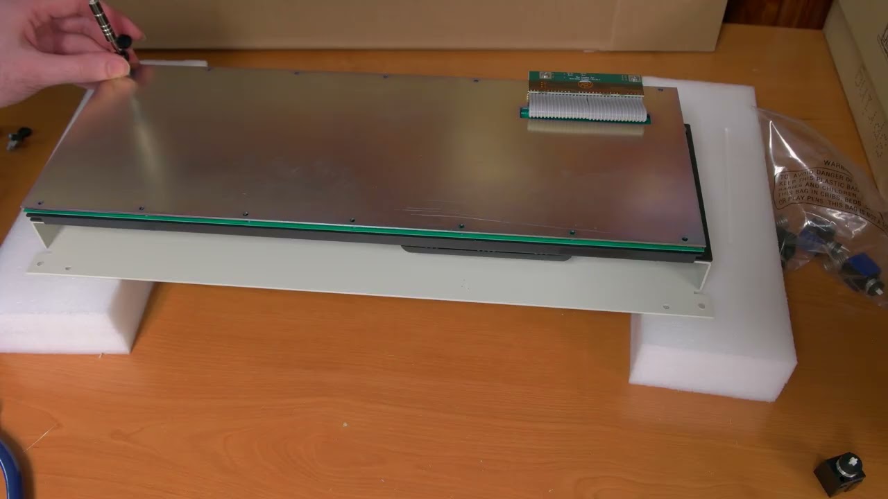
Re-sandwiching the foam, plate, and PCB. Proper tightness is crucial for the optimal beam spring acoustic signature.
This final setup videos show how to close the case. First make sure all the inner assembly bolts are back in place! If you flip the keyboard over without the bolts securely installed, then all the modules will fall all over the place! You are first putting the inner assembly back in place with its 4 bolts and washers. Then you reconnect the USB cable. There is one important difference with the B122 case (watch the first video below and then watch the second video if you have the B122).
🎬 Video — Closing the Case
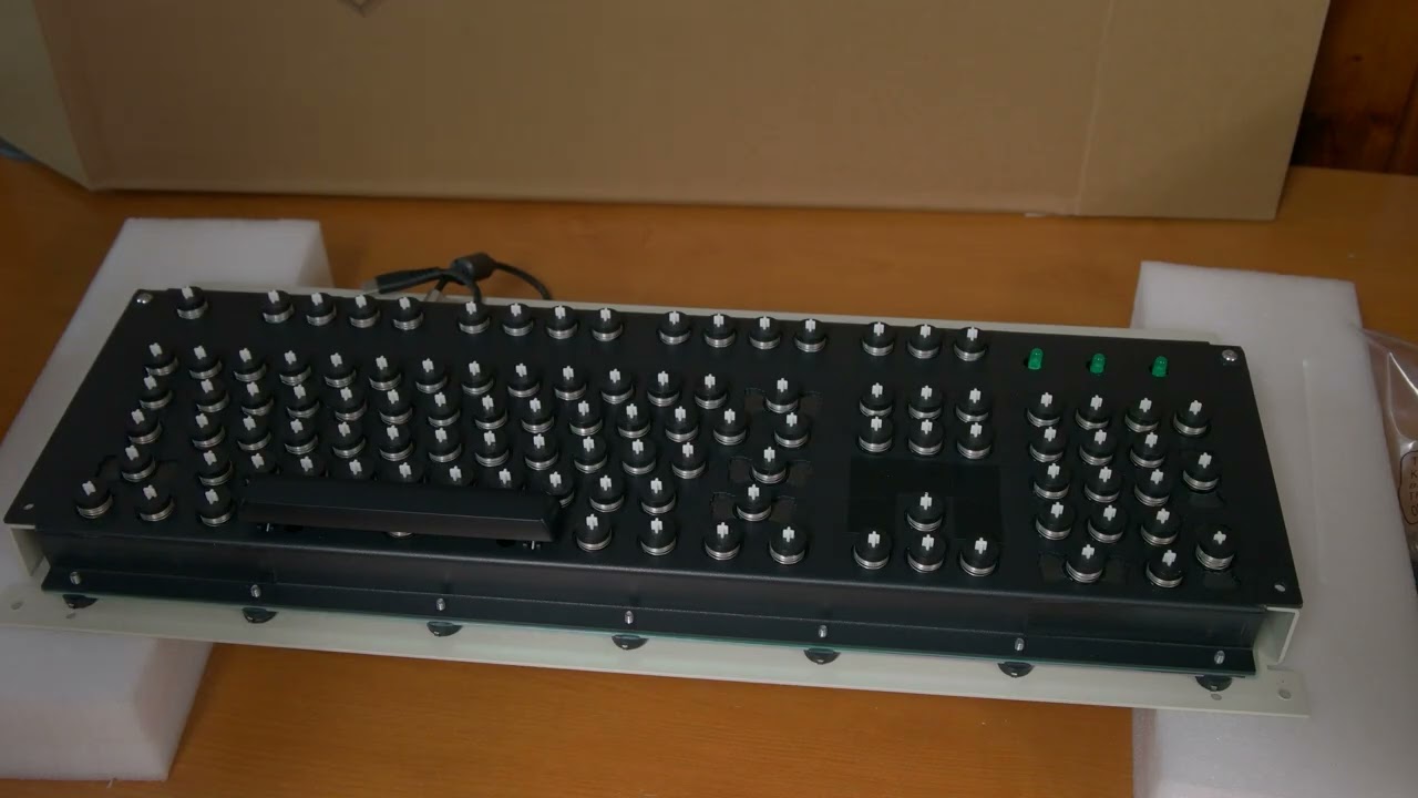
The final step: bolting the inner assembly to the top case and reconnecting the USB cable.
🎬 Video — Closing the B122 Case (important difference)
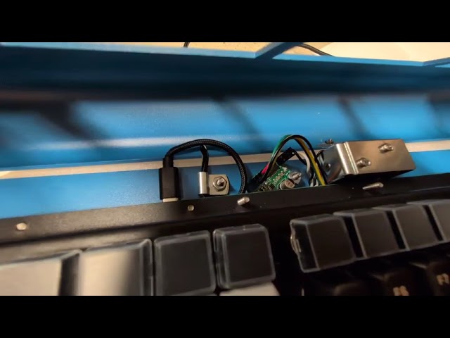
I recommend closing the B122 case as follows: place the curved lower part of the top case edge below the USB connector, then slowly lower the top case until it is in its normal position. It is ok that the case presses some of the keys while it is being closed. Alternatively you could install the keys after closing the case.
Design credit for the manual pages (as well as the reorganized content of the Model F manual) go to a helpful Model F user. Thank you!