Brand New Beam Spring Keyboards Round 1 Full Setup Guide
1. Important Notes & Main Videos
Looking for the Model F manual? Click here.
Looking for the Round 2 Classic Style Beam Spring manual? Click here.
1.1 Keycap Removal & Main Setup Video
Important Keycap Removal note (not in the video below): I use a wire key puller with gentle rocking motion and have no issues removing the caps. If you are using a lot of strength to pull them straight up or twist them, then you will most certainly break the modules and this will not be covered in the warranty (user damage).
Here is the step-by-step setup video for beam spring keyboards. Follow this video exclusively to set up your keyboard and perform troubleshooting. Please note that the Round 2 classic style keyboards do not require almost all of the maintenance and other setup steps in this video as was required by the Round 1 keyboards, for reasons explained on the Round 1 keyboard product page.
Always follow the important safety precautions as noted on the Model F and Beam Spring manual pages.
🎬 Video — Step-by-step setup video for beam spring keyboards

Follow this video exclusively to set up your keyboard and perform troubleshooting.
1.2 Typing Tests & Testing Modules
The next two videos show beam spring typing tests (first video link) and testing of beam spring modules (second link below).
🎬 Video — Beam Spring Typing Tests

Typing tests for beam spring keyboards.
🎬 Video — Testing of Beam Spring Modules

Testing procedure for the beam spring modules.
1.3 IBM Manual & Alternative Reattachment
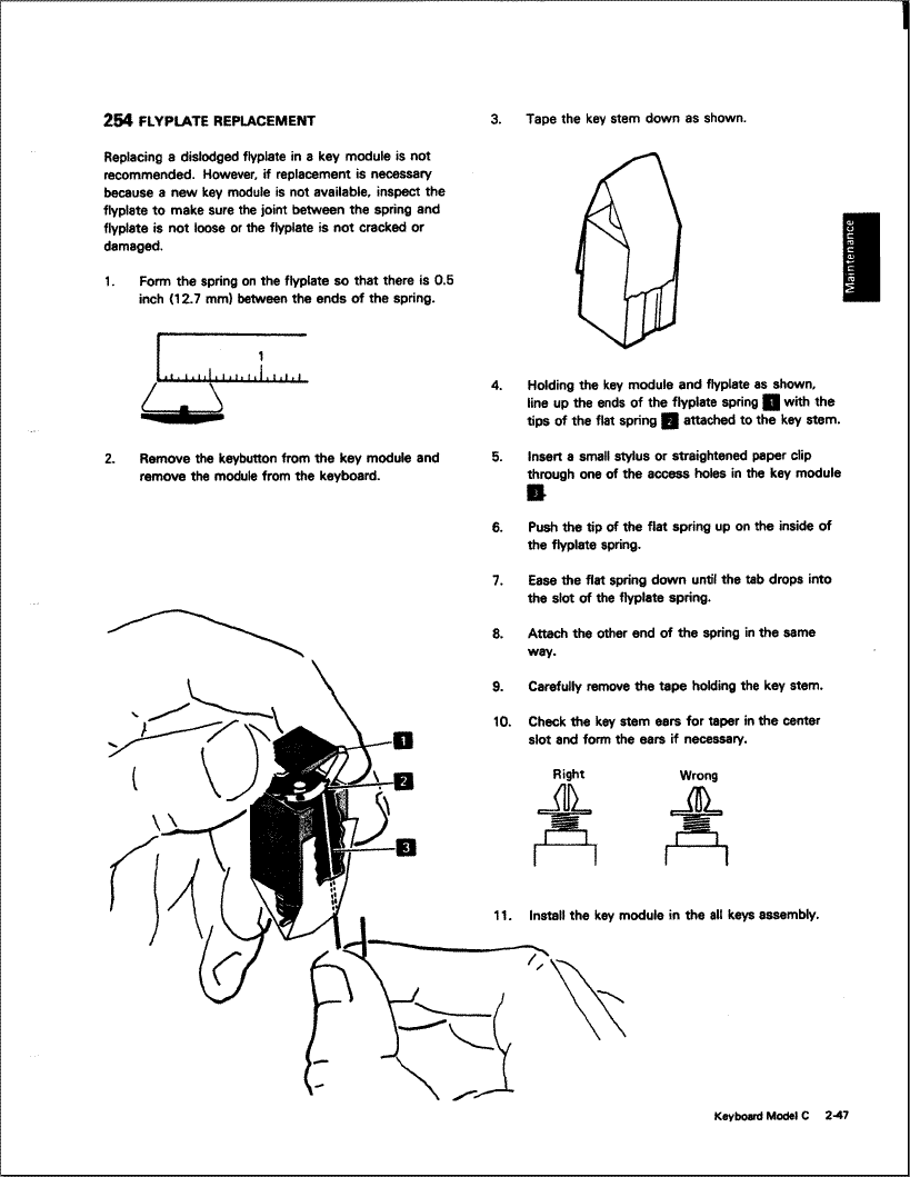
Only needed for old Round 1 boards with the metal washers on top of each module: This link shows a page from the IBM manual on how to reattach the beam module if the flyplate (beam metal part for beam flipper) detaches. This is by far the most common issue that comes up.
https://deskthority.net/wiki/images/c/ca/Manual3.gif
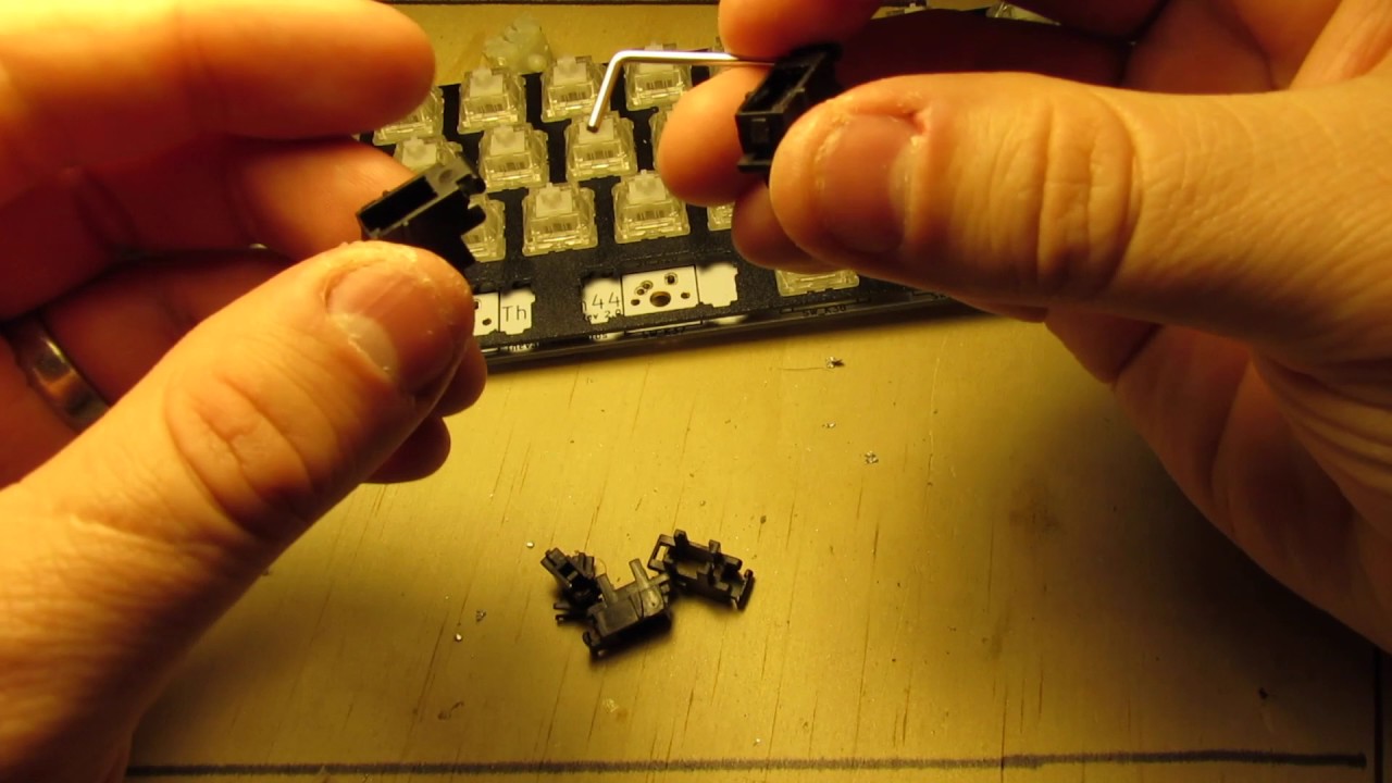
🎬 Video — Alternative way to reattach the flyplate

Alternative method for flyplate reattachment on Round 1 boards.
1.4 Press Fit Modules & Stabilizer Video
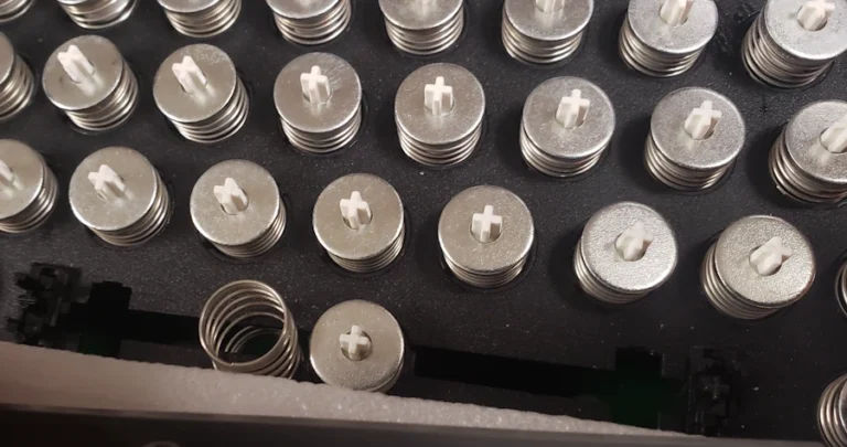
Note: the remaining Round 1 and all the Round 2 beam spring modules now have a press fit top instead of a glued on top, so it is extremely easy to take apart the beam module to quickly reseat a detached flyplate or flipper; no need to use the paper clip method. The main setup video shows this older glued washer, but just know that the module removal now is quite easy; see this section on how to take apart the module but still refer to the main round 1 setup video to adjust the metal flyplate. You can even remove and reattach the press fit top, spring, and o-ring without needing to open up the keyboard, which can sometimes fix an issue of a stuck key (just rotate the press fit top 90, 180, or 270 degrees or replace it, as very rarely the press fit top can cause the module to get stuck when pressed due to manufacturing tolerances.
This third party video shows how to assemble and install MX style plate mount stabilizer inserts, just in case yours fell out during setup (not common). As a note, this part should not snap in firmly for the beam spring keyboards, as it does in the example video. It should be loose and you should see the stabilizers move as the spacebar is pressed and released. The wire slides below the top of the plate while the plastic parts are inserted from above the plate. The reason is that the beam spring modules need extra movement to prevent them from getting stuck (a compromise to combine MX keys and beam spring modules).
🎬 Video — Assemble and install MX style plate mount stabilizer inserts
Third-party video demonstrating MX style plate mount stabilizer insert assembly.
Please note that the keyboard uses Torx T8 screws to prevent the screws from stripping, had they been + / Phillips head. I recommend getting a screwdriver kit with many bits.
2. Setup Walkthrough & Module Assembly
2.1 Initial Steps & Module Parts
Here is a partial script of the setup video for reference. As an important note, there are things in the video that have been added and/or changed after this script was created, so follow the manual and video primarily, and not the below script.
Take everything out of the box and inspect for damage.
This paragraph for old metal washer Round 1 keyboards only: A washer may have fallen off or become loose, so you probably want to glue it back on. Super glue is what I use. If you need to take apart the module for whatever reason, the washer can be removed. I recommend using the method in my video for bulk removal of beam modules.
Here is a video of how the beam module is assembled, for your reference (note: the Round 2 modules have a press fit top instead of a glued-on washer). The factory has 100% assembled everything for you already. Here are the parts of the beam spring module: beam barrel part A, beam barrel part B, metal part for the beam barrel, metal part for the beam flipper (the “flyplate”), flipper, spring, o-ring, and the washer. And here are the rest of the parts: controller, grounding wire, case (there is no separate inner assembly for the round 1 ultra compact beam spring keyboards), capacitive PCB, rubber sheet below the PCB, and the LED lights for the B104s and B122s only.
2.2 Testing Keys & Wiggle Method
As a note I will refer to beam module and key interchangeably – of course there is no key installed just yet on each beam module. Now we are going to test each key and note which ones to reattach once we open up the keyboard as required by the initial setup. Either the modules may have broken in shipping (rare), or the flyplate may have separated and need to be reattached. For these modules we will write down the ones we will need to adjust.
This paragraph primarily for Round 1 only: use the wiggle method to try to fix any of the stuck or sluggish beam spring modules; some modules may not be fixable this way. The beam spring wiggle method is performed as shown here, pressing down and using force to push the white part of the beam module clockwise, and then counterclockwise, about 10 times in each direction. If that does not improve things enough, then you can do the same wiggle method but with the key not pressed.
Round 1 only (not needed for Round 2): For the ultimate beam spring experience, you could even take off all the key modules to fine tune each one’s sound! Here is the quality control secrets part of this video, to increase the snappiness of the module if you prefer such a sound. The secret is to make slight adjustments to the metal part for beam flipper, which is part of the bottom flyplate part of the beam spring module. This is how the metal part should look like (see the setup video). There should be a fair amount of distance from the metal part’s bent curves to the flipper below it. Also the metal part’s wings should be equally spaced as shown, with about a half inch of space between them. Making them a little bit closer than this will make the beam modules more snappy, though too much may result in the module not working well.
Do not install the keys when doing this test as it will make the rest of the setup very difficult, for reasons you will soon discover.
From left to right, press each module many times. Try pressing it using different amounts of force to try to get it to become stuck, harder to press, or sluggish/slow to return up to the default position. Press with varying angles too. Do not worry if you notice that many keys require adjustments – you may have to adjust a lot more than you would with a Model F keyboard. Be careful with the space bar’s module as that module can only be switched with another trimmed module because the stabilizer wire is in the way (if this module needs replacement, just take it apart and replace all of the module parts except for the cut outer shell with parts from another module; this way you do not have to cut the new module). If a key module is acting up or is not consistent, you may need to press down on the press fit washer (the black plastic part on top of the beam module) all the way so that it is fully down as far as it will go on the beam barrel part B (the white part).
3. Opening the Case & Module Adjustments
3.1 Opening the Keyboard Case
Now it is time to open up the keyboard and adjust the nonworking keys you could not fix earlier. Put the keyboard upside down on its two foam inserts and open it up. Round 1 note: the controller and capacitive PCB are mounted to the keyboard bottom plate and it is attached by a grounding wire to the rest of the case, so be careful to just flip over the case as shown. Refer to your list and remove each module. Now you can see why we did not install the keycaps earlier, because it would have prevented us from easily removing each module. As a note the keyboard may now be reversed from left to right, so keep that in mind when removing the modules. At this time you should tighten the ground controller nut that is connected to the middle part of the case; if it is loose you will experience phantom key presses and other unwanted operation.
If you purchased a solenoid, see the solenoid installation section of the Model F manual. As noted on the solenoid product page, remember that the solenoid must be mounted externally for all Round 1 Beam Spring keyboards due to how huge the solenoids are!
3.2 Stuck Modules & Reattaching the Flyplate
Here is the process to fix a stuck module. While you can fix most stuck modules without having to remove the module, it’s easier to fix it with the module outside of the keyboard. Just like the Model F keyboards have a wiggle method to fix stuck keys, the beam spring keyboards also have a wiggle method. Note: stuck modules are very rare for Round 2 boards so the wiggle method is not likely to be needed at all.
The metal part for beam flipper is the most common part that falls out of place in any new or original beam spring keyboard. Here’s the process to reattach the flyplate, which consists of a metal part and a capacitive beam flipper. The beam spring mechanism works by lifting up the capacitive flipper when the key is pressed – this is the opposite of how the Model F keyboard works. In the Model F, the flipper is pressed down when a key is pressed.
Not needed for Round 2: here’s the process to fine tune the sound of the beam spring module. In my experience the sound can be fine tuned by adjusting the bend of the metal flyplate ever so slightly inwards or outwards, while taking care to replace or move to another key any key whose other inner metal part is permanently bent. For this reason it is very important to carefully remove the flyplate from this other metal part so as not to permanently bend or “crease” that part.
3.3 Stabilizer Trim & Module Orientation
To accommodate MX-style plate mount stabilizer inserts, the beam spring modules of the space bar has been trimmed a bit.
For all the keys except the space bar, these stabilizer inserts actually hinder operation of the keys and will make them get stuck in almost every instance, so they are neither recommended nor included. You should only use the space bar’s stabilizer insert and leave all others uninstalled. With the beam spring module design, even the widest Right Shift key functions fine and can be pressed even in the extreme corners without the stabilizers. The trimming has no effect on keyboard operation but they do not allow the key to “lock in” to the top of the case like all the other keys.
Each beam spring hole in the case is notched, so be sure to position things correctly when putting everything back into position. The notch should line up with the hole in the module. For reference you can see how your other modules are installed. The module may break if you do not pay attention to proper orientation of the module to fit the slot of the module and the notch of the top inner assembly.
4. Spacebar Setup & Troubleshooting
4.1 Spacebar Installation Methods
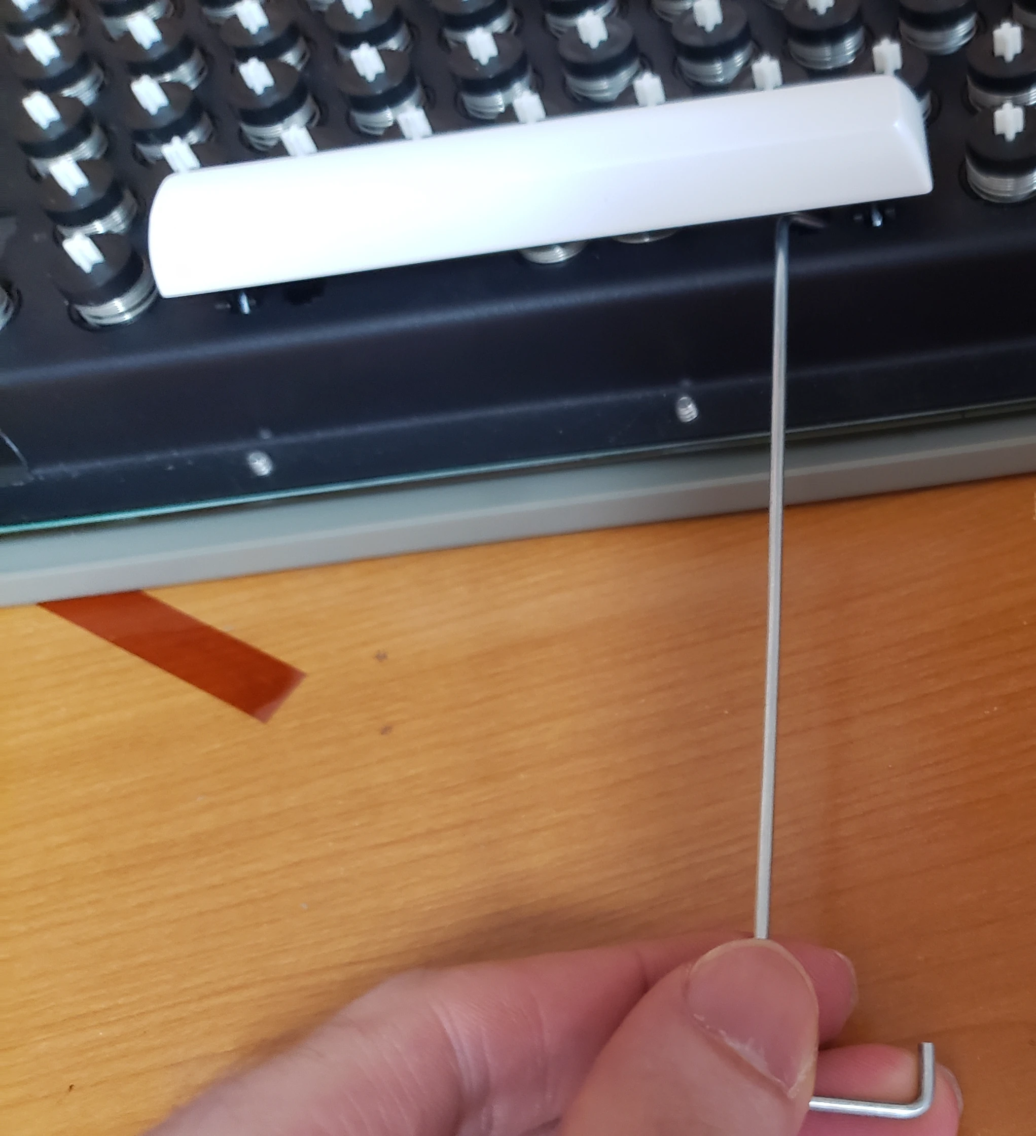
Next we are going to install the spacebar, which is the trickiest key to install. This key is preinstalled for all keyboards have a key set in the order. To adapt the old beam spring modules to have compatibility with Cherry MX style key sets, the space bar requires an MX plate-mount stabilizer insert (and for Round 1 only, an extra spring) to provide enough force for the space bar to return so it does not get stuck. Just like with the Model F keyboards, installing the beam spring space bar is more of an art than a science. You can either take apart the keyboard to install the spacebar safely, or you can use a bent metal part like a Model M or Model F spacebar stabilizer wire as shown to support the plastic MX stabilizer so that you do not break it while you are pressing the spacebar down on the MX stabilizer on each side.
4.2 Adjusting Spacebar Springs
Needed for Round 1 only, but you may want it for Round 2 if you prefer a heavier spacebar or the spacebar is not returning after it is pressed: We are going to insert the spare beam spring into the spacebar area shown and twist the spring a few times either clockwise or counterclockwise as needed. The more the spring is visible on top of the keyboard, the more force the spring will require to press it. I like 5 spaced out “rings” or turns of the spring to be visible, plus the 3 rings pressed together at the ends of each spring, so a total of about 8 rings. This gives the space bar a slightly heavier weighting than the other keys while reducing the chances that the force is not enough to have the spring return after it is pressed. If you prefer a lighter spacebar force, you can twist that spring so less of it is visible outside the keyboard, though as mentioned before if you do too little then the spacebar may not operate properly. After installing the spare spring or springs, attach the spacebar only to the beam module; do not press down on the MX stabilizer inserts. If the spacebar appears rotated so that one side is closer to the row of keys above the spacebar, then gently rotate the spacebar in the opposite direction. It may take a few tries before the spacebar is no longer significantly rotated. Please do let me know if you do any experimentation with the spacebar and have any recommendations.
We are not yet ready to test the spacebar just yet. Now we will push the 2 MX stabilizer inserts into the space bar. Be sure to push this as shown, with your finger pressing down on the plastic stabilizer part and your other finger below the spacebar as shown (or use the Model F/Model M spacebar stabilizer wire as shown). Be careful with this step as the plastic stabilizer is easy to break, however you can just replace it with a spare purchased elsewhere as they are interchangeable (for Round 1, the other stabilizers may have been trimmed on one side to accommodate tight placement with a 2U wide key’s beam spring module, though as noted before you should only use MX stabilizers with the spacebar and not with any other keys like backspace, enter, shift, or num pad 0. If you test pressing the spacebar in different areas and it gets stuck, twisting the spring to raise the number of visible rings or moving the extra spacebar spring towards the leftmost or rightmost side underneath the key may help (only do so after installing the spacebar to the MX stabilizer).
4.3 Safe Testing Practices & Troubleshooting
Very important – when testing the various keys after putting everything back, never test without screwing in all of the screws and putting the keyboard down on a flat surface. Do not test with the keyboard on top of the foam inserts. You may accidentally use too much force and push a module out of position. If a module falls out of the locked position in the top case, if you cannot nudge it back in place then the best option is to flip the keyboard upside down and put it on the foam inserts, open up the keyboard, and reseat the modules. To be safe, for the Round 2 boards I prefer to screw in the keyboard’s inner assembly upside down to the bottom case so that it is secured in place. Otherwise if the inner assembly falls out of place, the modules will fall out all over the place and you will have to reinstall every module by hand.
You may find that one side of the spacebar has separated from its stabilizer, maybe the space bar is not installed firmly onto the module, or maybe the spring needs to be twisted so it is higher or lower. If you find that the space bar is still not responsive or functional, you may need to follow the above wiggle method to fix a sluggish or stuck module, as it may make the module more smooth and fix issues you may be having. As a last troubleshooting step you can always switch the space bar module with the insides of one of your spare modules (remember you can’t just replace the spacebar module entirely because the housing is specially trimmed just for the spacebar module, but the rest of the beam spring module parts are all interchangeable). If this module’s outer black housing breaks then you’ll have to trim a new spare module in the same way to match the original spacebar module, using a tool such as a Dremel or other rotary tool kit.
It is normal for the space bar stabilizer to have some movement as the space bar is pressed – it helps with the space bar’s performance – do not glue or tighten this as you may make the space bar not work. If the space bar buzzes, try rotating the spring to a different ending position (i.e. not 360 degrees exactly but maybe 180 degrees, 90 degrees etc.).
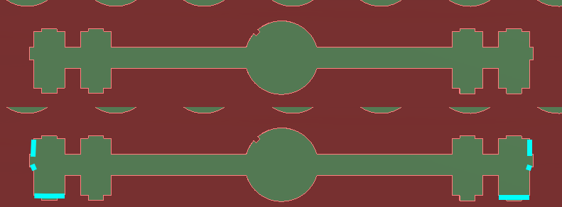
Take extra time to test pressing the spacebar from various angles and positions and with varying amounts of force, so that it never gets stuck or is slow to return to its full upright position. As detailed in the spacebar section, some looseness and movement is by design and considered normal, but it should not get stuck. I test every keyboard’s spacebar to make sure it is good, but you may find that some spacebars get stuck or are exceedingly hard to press. By design the spacebars should be a little harder to press than the non-stabilized keys. You should not need to do the following, but it is included in the manual for sake of completeness: what I do in these situations of a spacebar that is not good is (after the inner assembly is opened and bolted as shown later on) add 1 or 2 of the spare springs below the spacebar for extra support, as detailed in the next paragraph. If that doesn’t work, increase the amount of the spring that is above the TIA plate. Then replace the beam module itself. If that doesn’t work, I use a 3mm metal file (just do an eBay search for 3mm metal file set) to file two areas of the inner assembly stabilizer cutout: the bottom edge and the upper side of the outer edge, as shown below. Only file 0.5 to 1mm. Filing too much will make the spacebar excessively wobbly; a small amount of wobble is required as a compromise to adapt the slight looseness of beam spring module design to today’s MX key design. Better to file less and test (you have to close up the inner assembly fully and flip it over (see below instructions) to test the spacebar. The MX stabilizer should have a little movement by hand when it is installed in the inner assembly plate; test for this while filing. The top part of the below image shows what the spacebar looks like while it is upside down, and the bottom part indicates in cyan color which areas should be filed. As always, follow proper health safety protocols for filing aluminum, including protecting eyes and respiratory protection (file outdoors or with a proper mask, etc.).
5. Final Assembly & Software Testing
5.1 Closing the Inner Assembly
Once the spacebar is good, we can put the bottom plate back. Before doing this, check every module to make sure it is the same height with the other modules. A module that is slightly too high or not seated properly may affect operation of the keyboard. Install all of the screws and make sure everything is tight, but do not overtighten. The bolts should be so undertightened that you could squeeze the bottom and top inner assemblies together and they would move about 0.5 mm closer together. If you have screwed them so tight that the bottom inner assembly plate is looking curved or bent in the areas of the bolts then you have overtightened; you should loosen each bolt as needed so that the bottom inner assembly plate appears flat and has about 0.5mm of movement when squeezed by hand around all of the edges of the inner assembly where the bolts are located.
5.2 Dust Prevention
For best results, cover any holes with black electrical tape. It is best to keep dust out of the beam spring modules by covering the keyboard with a dust cover when not in use. For example, I have used the Fight Computer Dust Antistatic Vinyl Keyboard Cover (Keyboard Cover: 20W x2H x9D-Large). As with the IBM originals, dust affects the capacitive sensing so you may need to occasionally open up the keyboard inner assembly and use a microfiber / lint-free cloth to wipe the large capacitive PCB as well as wipe any flippers with visible dust. Do not use an air blower as you may blow modules out of place by accident. A big clump of dust may cause a key not to actuate reliably, or be recorded as pressed when the keyboard is first plugged in, resulting in the key being outputted continuously.
5.3 Signal Level Monitor
Now we will connect the keyboard to the computer to test each key with the pandrew signal level monitor utility and perhaps update the firmware. All of the required files can be downloaded here. First, open the utility. Next, connect the keyboard to the computer and click signal level monitor in the utility. At this stage I find it best to randomly press all of the keys using all of your fingers for a while to ensure that all modules are physically working correctly. I have found that this also helps to detect keys that are not detected reliably or are repeated when you press the key once, such as a key that appears to be stuck when you press it once but it constantly outputs a signal on the keyboard tester web site. (The fix for these issues require you to open up the keyboard inner assembly and wipe dust off the PCB and each beam module with visible dust).
6. Keycap Installation & Final Steps
6.1 Key Installation Best Practices
Key installation – never install keys with the keyboard on your lap or another uneven or soft surface, such as the protective foam packaging. Always install it on a hard flat surface like a desk. The reason is that you will be using force to press each key onto the module, and on a soft or uneven surface it could push the module out of place. While you are installing the keys, beam modules may also become stuck; lifting up the key with your fingers and then pressing it a few times usually stops the key from becoming stuck again. If that does not work, follow the wiggle method shown before while the key is installed, but this time be much more gentle. Be extremely gentle when pressing each key down to install it; you can easily break the white part of the beam module if you press too hard. When removing keycaps with a key puller, ensure that you are not also removing the washer and spring on the top of each beam module. The “arms” of the key puller should not be too close to the center of the module).
6.2 Transparent Relegendable Keys & Firmware Updates
My recommendation is to install all transparent relegendable keys with a piece of tape, saran wrap, or plumber’s tape between key and module so that you do not have to worry about it falling out. The worst that can happen is that the key won’t be able to be pressed down all the way because the key is already tight – in that instance, just remove the tape and install the key normally (though there are reports of keycap cracking – be careful!). Due to the variations of tolerances between key stems and keys, occasionally a key may fit so loosely that it falls off easily. I have not seen this issue at all with the project’s full key set but it may happen with other MX key sets. I have also seen this with the transparent relegendable MX keys being sold with the project since their tolerances do not appear to be as tight. This means that if you purchased these relegendable keys or other manufacturers’ keys, it is possible that some keys will fall off if you hold the keyboard upside down or while typing. There are various safe fixes for this, such as putting a piece of paper or scotch tape between the key cap and the beam spring module’s stem, which you may need to do as you set up this keyboard. These fixes will completely stop any loose keys from falling out.
To update your keymapping and/or firmware, please refer to the xwhatsit firmware section of the Model F manual.
Design credit for the manual pages (as well as the reorganized content of the Model F manual) go to a helpful Model F user. Thank you!