Brand New Model F Keyboards — Manual
Looking for the Round 2 Classic Style Beam Spring manual? Click here.
Looking for the Round 1 Compact Style Beam Spring manual? Click here.
⚡ Quick Start Guide
After the required initial preparations and learning, here’s an overview of what you’ll be doing:
- Inspect your shipment — check all parts are present, no damage. See Section 3.1.
- Install stabilizer inserts — white (horizontal) for 2U+ keys, black (vertical) for numpad/ISO Enter. See Section 3.2.
- Set up the spacebar — test actuation, bend wire if needed. See Section 3.3.
- Inspect all springs — should be at 12 o’clock position, ~1mm from barrel edge. See Section 3.4.
- Install keycaps — hold keyboard vertically (spacebar up), test each key for a click as you install. See Section 3.5.
- Connect and test — plug in, use a keyboard tester, then pandrew/Leyden Jar Signal Level Monitor. See Section 3.6.
- Fix any issues — refer to the Troubleshooting section below.
1. Before You Start
What Makes the Model F Special
- Capacitive buckling spring technology — no metal-on-metal contact means extreme longevity
- Every single part is user-replaceable with basic tools and the foresight to teach yourself how to maintain a Model F and to buy spare parts now for use long after the project has shut down: Buy It For Life
- Dye-sublimated PBT keycaps — legends don’t wear off
- Full N-Key Rollover (NKRO) support via QMK/Vial firmware
- Metal construction — 5–10 lbs per keyboard, built to last decades
- Heavy-duty inner assembly “sandwich” plates with interlocking tabs
The Deal
These keyboards require hands-on setup. Keys will not all work out of the box — that’s normal and expected. The Model F and Beam Spring keyboards are a Precision Component Assembly. Because of the limitations inherent in small-batch manufacturing and the high G-force drops sustained in shipping, these keyboards are intentionally delivered in a non-final state. Transit displacement is not “damage.” You’ll spend 30–60 minutes setting things up properly. For this keyboard, “Final Assembly” happens at your desk. Keyboards come mostly assembled (basically everything except keys and accessories) but the setup process involves following the steps in the manual on this page to get everything working, such as adjusting springs and using a signal level monitor program to test keys. Physical adjustment is a required part of setup. This isn’t a defect; it’s the nature of buckling spring technology. Once set up correctly, you’ll have a keyboard that can genuinely last a lifetime.
Key Rules
⚠️ Do not skip steps or jump ahead. Read the entire step before starting the work in the step. Each step builds on the previous one. Skipping ahead or thinking you know what to do because you have used a Model F, Model M, or other mechanical keyboard will almost guarantee that you will break something or have to spend much longer to redo things the right way. Folks have told me they literally spend an hour on something that they realized after reading the manual that it would take a minute.
⚠️ Do not email me or post on forums if something appears wrong. You must follow the manual first. (support is not available by phone). Many support emails I receive are from folks who didn’t read the manual and made some mistakes. The manual will say when you may reach out for support and what specific diagnostic steps taken and screenshots (like the Signal Level Monitor) you need to include.
⚠️ No single fix should take more than a few minutes. If you’re spending an hour on something, stop and re-read the relevant section.
⚠️ Do not plug the keyboard into your computer until Step 3.6. Only use the USB cable that came with the keyboard, as not all USB cables are compatible or safe, especially the “smart,” Apple, or “E-Marked” USB-C cables.
⚠️ Read your keyboard’s product page to understand the various details, options, and recommended add-ons, and the condition the keyboard and its parts are expected to arrive in, so that your expectations are in line with the project’s longstanding policies.
⚠️ Safety warnings: Always consult the booklet included with your new Model F keyboard for safety precautions and other important information. Severe harm or even death can occur with any product if safety precautions are not followed.
🎬 Video Guides — Getting Started

Step 1: Overview — What makes the Model F special, project philosophy, why setup matters, and what to expect from the process. Watch this before opening the box.
Step 1 continued: Safety precautions, recommended spare parts, tools you’ll need, and the project’s repair-for-life philosophy.
2. Parts & Tools
Parts Identification
Every Model F keyboard is made of the same core components. Familiarize yourself with each part before starting assembly.
Keys / Keycaps
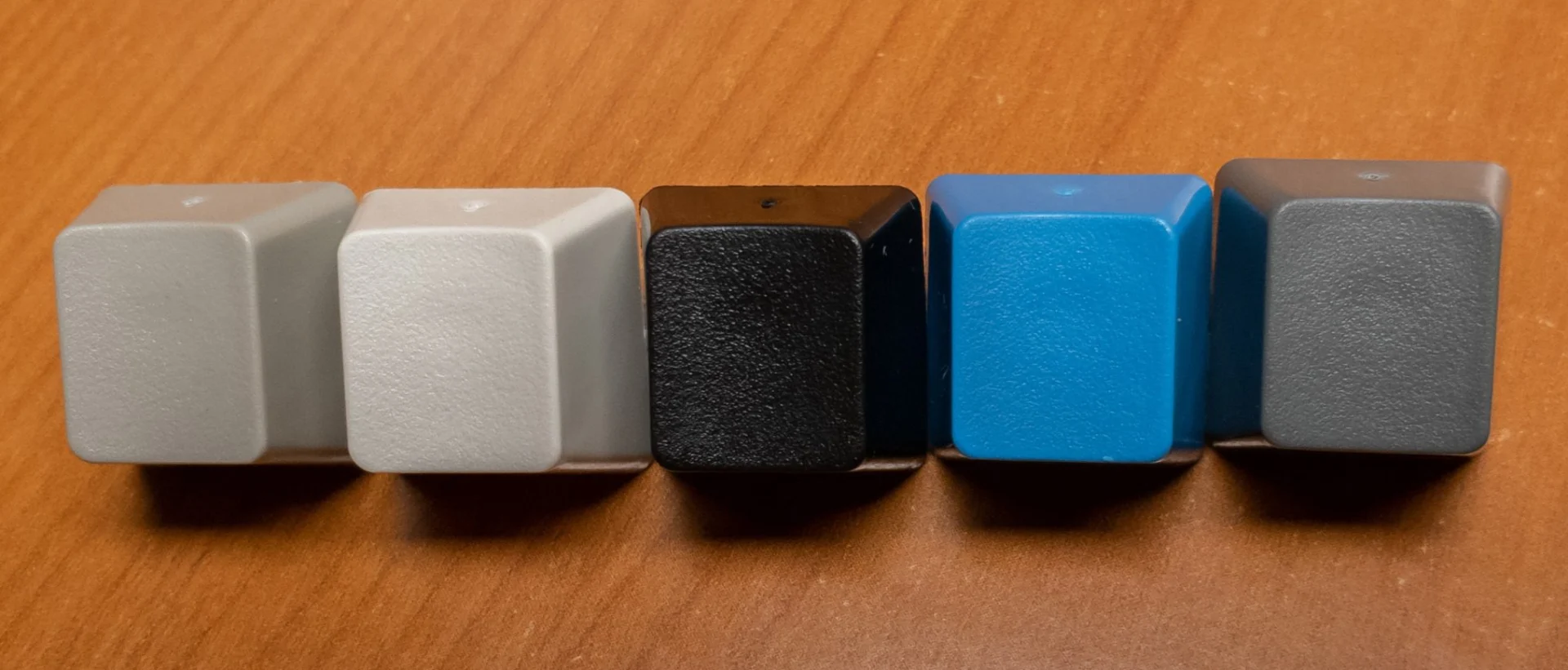
PBT dye-sublimated caps in various colors: Pebble, Pearl, Black, Industrial SSK Blue, 60% Dark Gray. Legends are printed through the plastic and will not wear off.

Barrel
Individual injection-molded housing for each key. The barrel holds the flipper, spring, and keycap in alignment. Empty barrels at stabilizer positions are intentional.

Flipper with Spring
The buckling spring mechanism — sits inside the barrel. The spring buckles when pressed, actuating the capacitive sensor below. This is the heart of the Model F’s feel and sound.
Top Inner Assembly
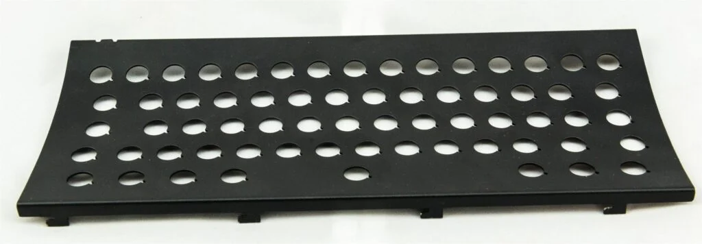
Upper metal plate of the inner “sandwich.” Holds all the barrels in position. Interlocking tabs connect it to the bottom inner assembly.
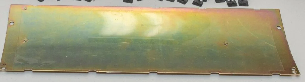
Bottom Inner Assembly
Lower metal plate. Houses the capacitive PCB and controller. The foam sits between this plate and the top assembly.

Inner Foam
Sits between the assembly plates and keycaps. Reduces dust ingress and barrel wobble. Loses resiliency over time when compressed — order spares while available.
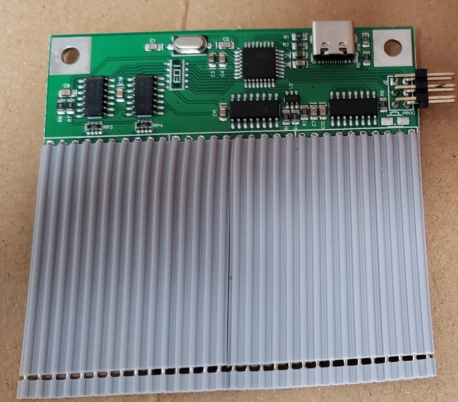
Controller PCB
xwhatsit or Leyden Jar controller with ribbon cable. This is the brain of the keyboard — handles key scanning, USB communication, and firmware. Connected to the capacitive PCB via ribbon cable.

Large Capacitive PCB
Sensing PCB that sits underneath all keys. Detects the capacitive change when a spring buckles. No physical contact needed — this is why Model F switches last virtually forever.

Case (Top & Bottom)
Powdercoated metal case in two halves. Available in zinc (heavier, deeper sound) and aluminum M-style (lighter). 5–10 lbs total depending on model.

Solenoid (optional)
Adds a tactile thud and audible click to every keypress. Powered by the solenoid driver board. See Section 5 for installation.
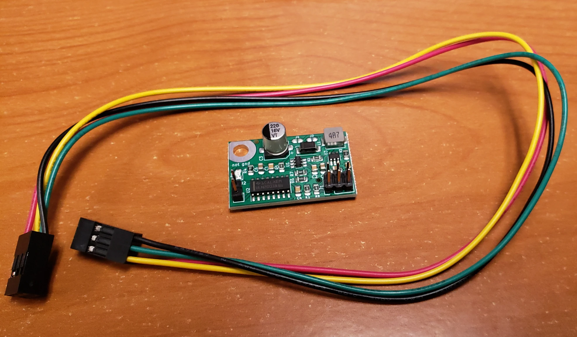
Solenoid Driver (optional)
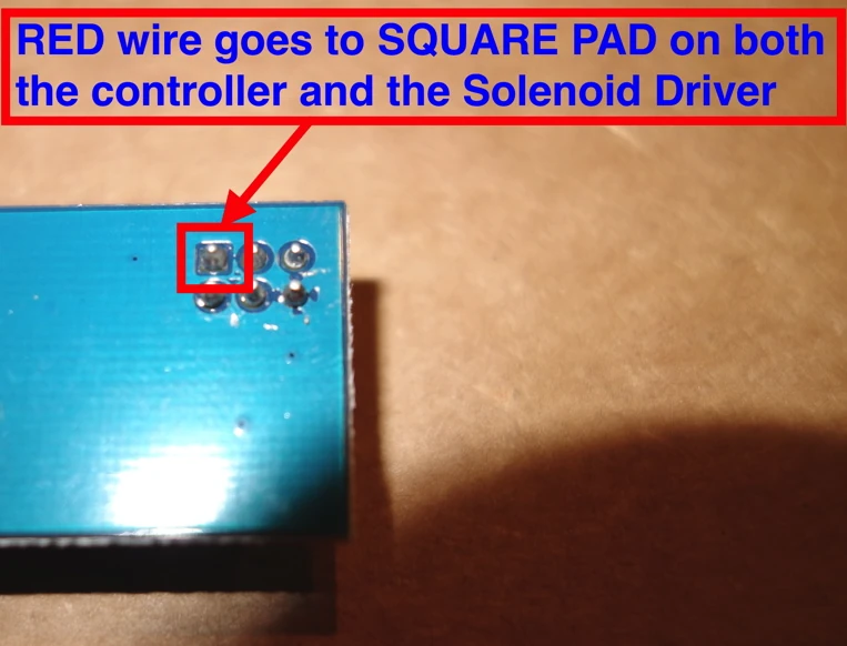
Required board to power the solenoid. Connects between the controller and solenoid via cable. Must be oriented correctly (square pad to square pin) or it will be destroyed.
🎬 Video — Parts Identification

Parts Identification: Visual walk-through of every component — keycaps, barrels, flippers, springs, inner assemblies, controller PCB, capacitive PCB, case, solenoid, and solenoid driver.
Required Tools (no tools are included)
- Precision screwdriver set — Phillips + and Torx T8
- Wire keycap puller — essential for safe key removal
- Tweezers — for adjusting springs
- Tongue and Groove (Channellock) pliers — for opening/closing inner assembly
Possibly Required Tools
- Basic soldering iron — for ribbon cable touch-ups (rare)
- 2-inch C clamps (5+) — for reassembling larger keyboards (F104, F122, FSSK)
Recommended Spares
Order these while they’re still in production — they won’t be available forever:
- First Aid Kit of spare parts
- Extra flippers with springs
- Spare barrels
- Extra keycap sets (PBT wears over years)
- Spare 3-meter USB cable
- Extra inner foam (loses resiliency over time when compressed)
🛒 Where to Buy
From Model F Labs (spare parts specific to your keyboard):
- First Aid Kit — spare springs, flippers, barrels, and more
- Wire Key Puller Tool
- Solenoid + Solenoid Driver (optional add-on)
- Full Model F Store — spare keycaps, USB cables, bumpers, and more
From Amazon (general tools):
3. Setup Step-by-Step
3.1 Inspect Your Shipment
Do this within a few days of delivery, before starting setup.
- Check all bags — parts may be mixed between bags
- Verify keycaps — look for chipped or broken stems. Don’t use damaged caps. If one keycap’s bottom leg (the stem) appears chipped and does not look like all the other stems, do not use it.
- Install the 4 bumper feet — keyboard must be used with feet installed
- Check springs on flippers — move each spring with your finger to verify free movement
- If a spring is stuck: gently nudge flipper with tweezers
- If a spring is missing from a flipper nub: see Spring Adjustment (Section 3.4)
- Empty barrels (without flippers/springs) are intentional — wide keys use stabilizer inserts in those positions
- Verify your layout matches what you ordered:
- Full Left Shift: no flipper in right barrel
- Full Right Shift: no flipper in left barrel
- Standard horizontal Enter (US): no flipper in left barrel
- ISO Enter: no flipper in top barrel
- Split Backspace: flipper in both barrels
- 2U Backspace: no flipper in left barrel
- Wrong layout? Change it now before installing keys — it only takes a few minutes with no keys installed. (You can’t switch between HHKB split right shift and regular right shift without different parts, though a combined part is planned for the future.)
- Only after inspecting every part when your keyboard is delivered, if something broke in shipping you can email me so it can be replaced as part of the limited warranty. After you are completely finished with setup, send one brief email with a couple photos; do not send multiple emails (you can temporarily install another key if one is damaged, for example). I go through thousands of emails and need your help to stay organized.
- Remember that if just some keys are broken, continue installation and put spare keys in those key positions on the keyboard. Do not stop and wait for replacement parts because you need to make sure everything else is good with what you ordered. You can put a 1U key in a larger key spot, for example.
🎬 Video — Inspecting Your Shipment
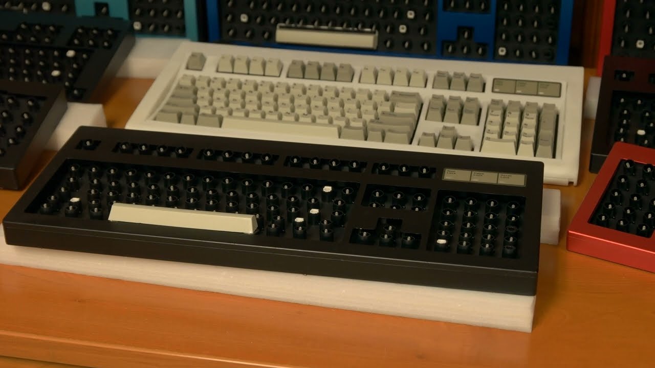
Inspection: How to check your shipment — verify keycaps, springs, flippers, layout, and identify any shipping damage before you start setup.
3.2 Install Stabilizer Inserts
Do this before installing any keycaps.
Identify Your Inserts

| Insert | Color | Orientation | Used For |
|---|---|---|---|
| Horizontal | White (usually) | Ears on left and right | 2U+ horizontal keys (not spacebar) |
| Vertical | Black (usually) | Ears on top and bottom | 2U vertical keys, ISO Enter |
On rare occasions (such as for the F Split Ortho), the horizontal white insert may perform better with 2U vertical keys than the vertical insert.
⚠️ Color isn’t always reliable. Check the ear shape — uneven ears = vertical insert, regardless of color.
⚠️ Don’t put an insert in a barrel that has a flipper. You’d need to open the keyboard to remove a flipper.
Installing Horizontal Inserts (White)
- Orient with cavity number at 12 o’clock (closer to top row)
- Ears face left and right
- Press all the way down — top of insert should be flush with top of barrel
Installing Vertical Inserts (Black)
- Start with insert ~1mm above the barrel top — easier to push down than pull up
- For number pad 2U vertical keys: larger ear on the right
- For ISO Enter only: larger ear on the left (rotated 180° from other vertical keys)
- Inserts require significant force to insert — use a tool to gently tap them in
- For ISO Enter specifically: push the insert all the way down (below barrel top) for reliable operation
If an Insert Needs to be Removed
Options (from least to most invasive):
- Safest option: Remove all keys, open inner assembly, push insert out from the other side (does not harm insert if done properly). This is why you install the few stabilized keys first and make sure they are good before installing all the other keys.
- Deskthority method — remove without opening keyboard (does not harm insert)
- Wilde Tool G407 lock ring pliers — can grip and pull inserts (leaves small teeth marks inside, but should not affect operation; squeezing the tool handles too much can crack the barrel and insert)
- 1/4-20 inch thread tap — fastest option; screws into the insert for removal (insert is destroyed; be sure you have spares)
🎬 Video — Installing Stabilizer Inserts
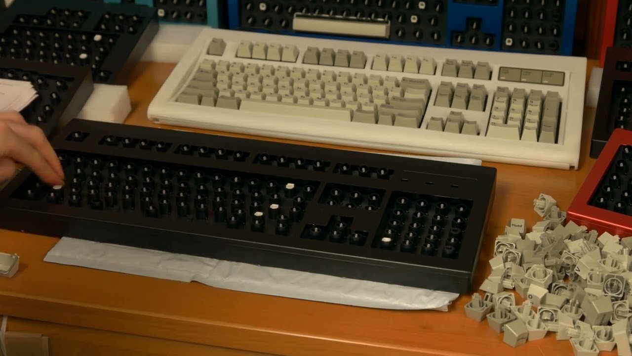
Stabilizer inserts: How to tell horizontal (white) from vertical (black), correct orientation for each key size, how much force to use, and what to do if one gets stuck.
3.3 Spacebar Setup
Do this before installing other keys — it’s harder to adjust later.
Basic Test
Press the spacebar many times at different angles and positions. Listen to the sound and feel. Make sure it doesn’t get stuck.
If Spacebar Doesn’t Actuate
- Test with a 1U key to confirm the spring/barrel are good
- Carefully remove and reseat the spacebar (may take several tries); ensure you feel the spring buckling when pressing the spacebar
- If it gets stuck on the edge of a metal spacebar tab: push down slightly on the tabs
Bending the Stabilizer Wire
The stabilizer wire often needs adjustment after shipping:
- Remove the wire from the spacebar first — hold spacebar upside down, keep wire flat against it, pull from one end. Never pull straight off.
- With two hands, thumbs on the long part of the wire, gently push up 4–8 times
- Goal: ~1mm gap between wire and back of metal stabilizer tabs
- Wire should be underneath the top of each metal tab
- Too much gap = rattly but lighter action (and the
> .key may contact the wire) - Too little gap = heavier action and possible sticking
- If the spacebar wire contacts the
> .key, bend the wire closer to the back of the metal tab, or bend the spacebar in the other direction. - For smaller spacebars, use lock jaw pliers set to 1 inch width to squeeze the spacebar and make its right short side ~22mm instead of ~23mm.


Tightening the Wire
- Remove wire, squeeze the left and right ends inward slightly with pliers (if these left and right ends are too far apart from each other, pressing the Alt keys may contact the spacebar).
- Don’t over-tighten — you need to be able to reinstall it
Adjusting Metal Tabs
- Push tabs down slightly = less rattle, heavier spacebar force
- Push too far = spacebar gets stuck frequently
- To re-raise tabs: remove nearby keys, nudge wire toward spacebar with screwdriver
- For replacement tabs: use the tabs with the smooth, non-bumpy side touching the inner assembly plate. Never try to bend the tab’s vertical back side.
- If the spacebar is making contact with the keys above it, put some scrap foam or card stock vertically between the spacebar stabilizer wire and the back of the metal tab.

Community Tips for Spacebar Rattle
- Setting expectations: Rattle is normal due to 1980s tolerances and metal-on-metal contact; the spacebar may rotate 1-2mm in various directions. Plastic would be quieter but far more prone to breakage.
- Electrical tape where stabilizer meets clips
- Heat shrink tubing on wire
- Thin adhesive neoprene under wire near tabs
- Clear plastic tube where wire touches tabs
- Silicone grease on friction points (lightly!)
- O-rings at base of spacebar barrels (16mm OD, 12mm ID, 2mm thick)
- Self-adhesive rubber strips inside spacebar
- Poron ThinStik polyurethane foam strips on top plate where wire contacts it
🎬 Video — Spacebar Setup

Spacebar adjustment: How to bend the stabilizer wire for optimal feel, adjust metal tabs for less rattle, tighten or loosen actuation force, and fix a sticky or squeaky spacebar (hint-adjust, reseat, or replace the spring to reduce squeakiness).
Changing spacebar size: You can install a large new Model F spacebar on a keyboard configured for the medium spacebar, but the reverse can’t be done unless you open up the keyboard to add a barrel and flipper with spring. To go from smaller spacebar to larger spacebar, you don’t have to remove the 1.25U key’s barrel and flipper with spring; just be sure to set this 1.25U key to no function in Vial (KC_NO) if doing that. The spacebar should be installed with its end up at a 45 degree angle.
3.4 Spring Inspection & Adjustment
This is the single most important skill for Model F ownership. If you need to remove or reinstall a spring right now, jump to How to Remove & Reinstall Springs below.
How Springs Should Be Positioned
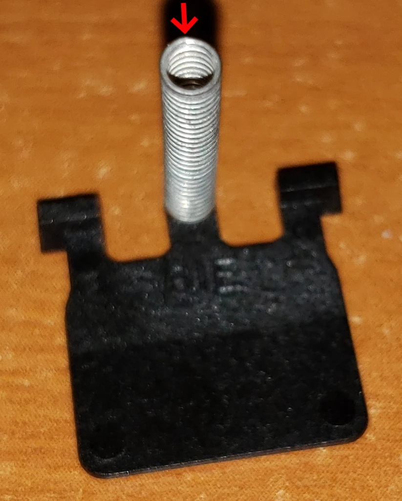
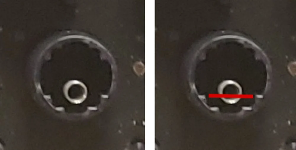
- Spring end at 12 o’clock position relative to the flipper
- Spring should sit about 1mm from the barrel edge (close to touching)
- Spring must be fully pressed down onto the flipper nub
Inspecting All Springs
- Hold keyboard vertically, spacebar side up
- Look at every spring position
- Springs close to the barrel edge = good
- Springs toward center of barrel = need adjustment
- Do keys near one of the keyboard edges get stuck? Loosen the screws on the bottom case and slide the inner assembly away from the edge. Make sure the inner plates slide in fully so the tabs touch the sides of the bottom inner assembly. The top left tab should be folded down a little to lock everything in place.
Adjusting a Spring
- Remove: Twist gently counterclockwise (looking straight down). Never pull straight up.
- Reinstall: Using tweezers, position the spring on the flipper nub and push straight down without twisting. Press firmly until fully seated. (Attempting bare-hand reinstallation risks the spring flying out and being lost permanently. Tweezers are essential for reliable placement.)
- Position: End of spring at 12 o’clock, ~1mm from barrel edge
- Flip it: If a spring isn’t working well, try installing it upside down
- Replace it: If flipping doesn’t help ensure reliable keypress operation, swap in a spare spring. Damaged springs can’t be fixed.
A spring may look fine but not work. You can’t judge by appearance alone.

🎬 Video — Before Installing Keys

Spring inspection: How to check spring positioning before installing keys, the correct 12 o’clock orientation, how to remove (twist CCW) and reinstall springs, and the QC secrets for testing each key.
3.5 Install Keycaps
Order of Installation
- 2U and larger keys first — they’re most likely to bind and may need the Wiggle Method. If a larger key gets stuck, stop and adjust until it is 100% reliable; don’t think you can proceed and go back later since you may have to remove all those keys you installed to start over.
- All remaining keys after large keys are confirmed working.
How to Install Each Key
- Hold keyboard vertically, spacebar side up
- Check the bottom of each key — stems should look uniform (except 2U vertical and ISO Enter)
- Don’t install damaged keys
- Press each key in slowly — fast insertion can bounce the spring out of position
- Test each key for a reliable click as you install it
- Listen for the snap of the flipper — if you only feel spring pressure without a snap, the key isn’t properly installed
- Don’t lay keyboard flat until all keys are installed and tested
- If you install screw-on bumpers, note that for the F122, do not use the 2 attachment points that are covered by these bumpers (leave those holes empty).
- Do not connect the keyboard to a computer until you have installed the keys. Per a DT user: “When there are no keycaps, all the flippers will rest on the pcb giving you pressed keys all over.”
🎬 Video — The Wiggle Method
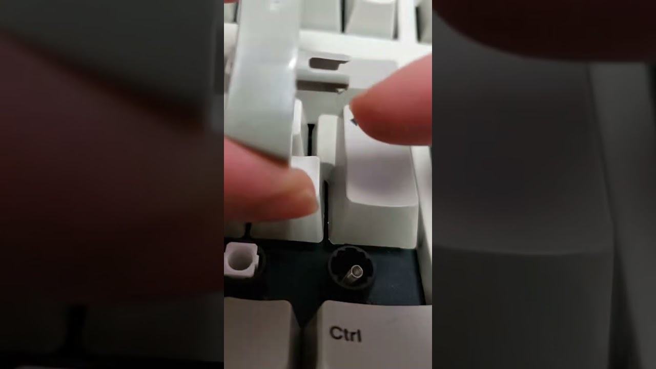
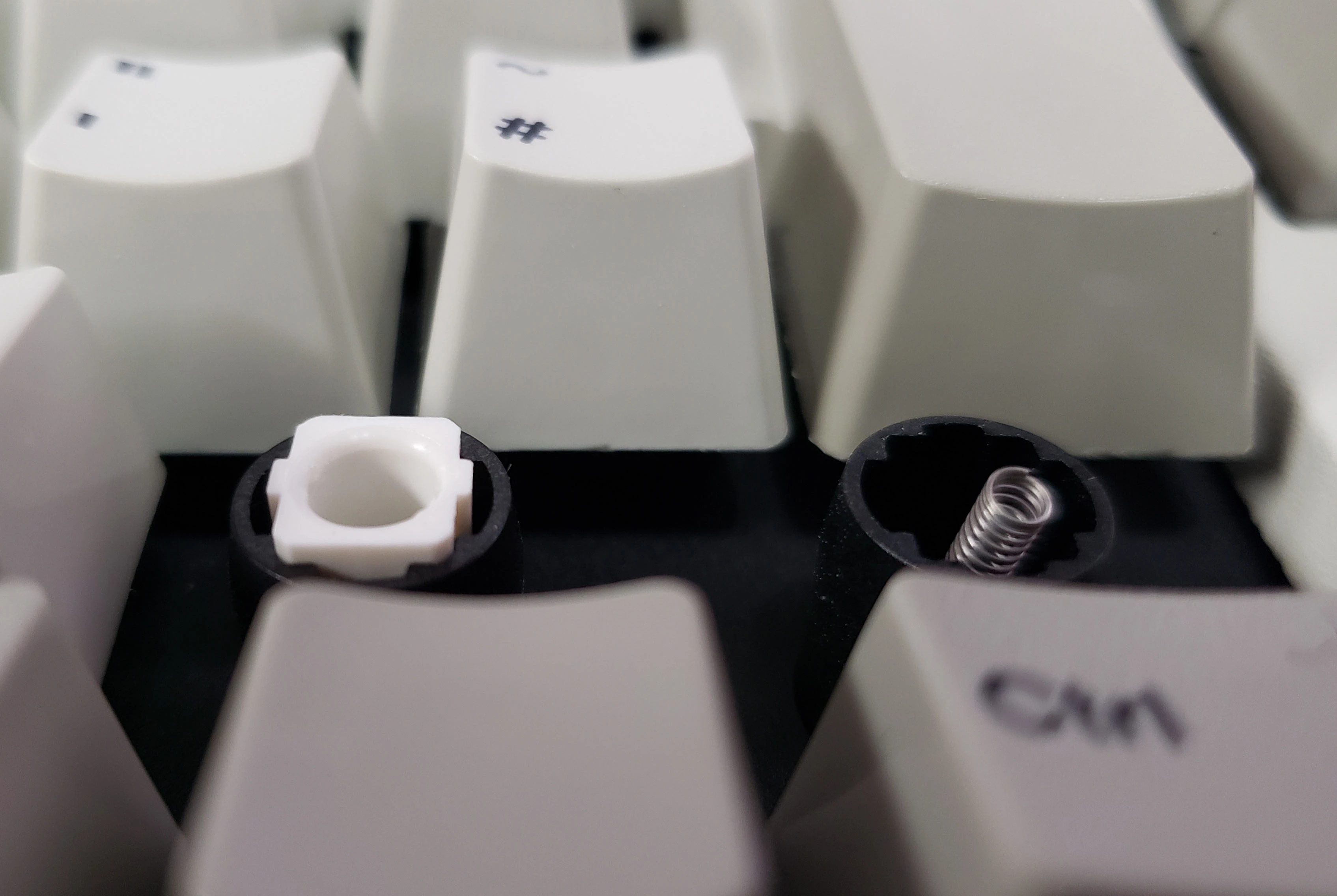
Wiggle Method: Step-by-step technique for fixing stuck 2U and larger keys — stem squeezing, post wiggling, burnishing, and when to widen stems. Only for stuck keys, not non-clicking keys. Other potential fixes for stuck keys: Paint a little Krytox 105 on the inside of the black stabilizer, or add a little bit of Syncro Superlube. Add a 1mm piece of foam under the side of the key where the stabilizer insert goes.
3.6 Connect & Test
Pre-Connection Checklist
- ✅ Every key position has a key installed (no empty spots)
- ✅ Every key snaps/clicks when pressed
- ✅ Keyboard has been held vertically during all installation
First Connection
- Plug directly into computer — not through a USB hub
- Disconnect all other USB devices except mouse (for troubleshooting)
- Check Device Manager (Windows) / System Information (Mac):
- Should see a keyboard device
- If you see “ATMEGA32 DFU” or “RPI-RP2” → firmware needs reflashing (see Section 6)
- If nothing appears → see Section 4.3
Testing Keys
- Go to an online keyboard tester and press every key several times
- Then use a typing test site like 10fastfingers to make sure there are no occasionally non-working or transposed keys.
- One key won’t register on testers? It’s probably the Fn key — this is normal:
- HHKB layouts: key right of shorter right shift
- Latest non-HHKB firmware: key between Right Alt and Right Ctrl
- Older firmware: Right Ctrl
Mac Users
A keyboard configuration popup should appear on first plug-in. If not:
- System Settings → Keyboard → Modifier Keys
- Swap Command and Option in the dropdowns
- No need for Karabiner unless you want additional remapping and cannot use the Vial GUI
💡 Tip: Unplug keyboard for 15+ minutes between testing sessions. Replug often fixes intermittent issues. A cold reboot can also help.
4. Troubleshooting
Before diving into specific issues, start here. The quick reference table covers the most common problems, and the ground screw check resolves the majority of them:
⚠️ Critical: Check Ground Controller Screws
While experiencing bumps and drops in transit, the two screws grounding the controller to the bottom inner assembly often loosen. This is one of the most common causes of:
- Key transposition (two keys typed fast switch places)
- Double key presses
- Intermittent dead keys
- Keys not registering when modifier keys are held, or entire keyboard not detected
How to fix: With the keyboard upside down, locate the two screws securing the controller PCB to the bottom inner assembly. Tighten both screws while ensuring the controller’s silver ground tabs align exactly with the silver ground area on the bottom plate. The two squares must line up perfectly. If the gold bottom inner assembly plate’s ears contact the pad for the resistors next to the USB connector, the keyboard won’t be detected.
Do this before troubleshooting any key issues. It takes 30 seconds and fixes the majority of problems.

Troubleshooting Quick Reference
| Symptom | Likely Cause | Quick Fix |
|---|---|---|
| Key doesn’t click when pressed | Spring misaligned or damaged | Remove key, twist spring off (CCW), reinstall at 12 o’clock position ~1mm from barrel edge. If still fails, try flipping spring upside down or swap with another key’s spring. → Section 3.4 |
| Adjacent keys transpose when typing fast | Spring needs reseating; or ground screws loose | First tighten ground controller screws. Then reseat the springs of both affected keys. |
| Key works then goes dead mid-session | Debris on capacitive PCB, or ground screw issue | Tighten ground screws. Adjust, remove, or replace spring. If persists, blow compressed air at the affected key. Last resort: open inner assembly and clean PCB and flipper with lint-free cloth. |
| 2U+ key gets stuck when pressed | Stabilizer insert or keycap binding | Use the Wiggle Method: squeeze stem/post 20–30 times, then burnish back of stem with fingernail. Do NOT sand or lubricate. |
| Key registers double presses | Spring not fully seated on flipper nub | Reseat spring — push all the way down onto the nub, position at 12 o’clock, ~1mm from barrel edge. → Section 3.4 |
| Spacebar sticks or rattles | Stabilizer wire too close to/far from metal tabs | Bend wire slightly (0.5–1mm) away from back of metal tabs. See Section 3.3 for detailed adjustment. |
| Keyboard not detected by computer | Firmware cleared or USB issue | Check Device Manager for “ATMEGA32 DFU,” “RPI-RP2,” or “Unknown USB device (Device descriptor request failed)” → reflash firmware. Try different USB ports. No hub/KVM. Check controller alignment. |
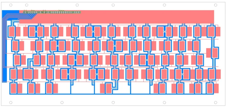
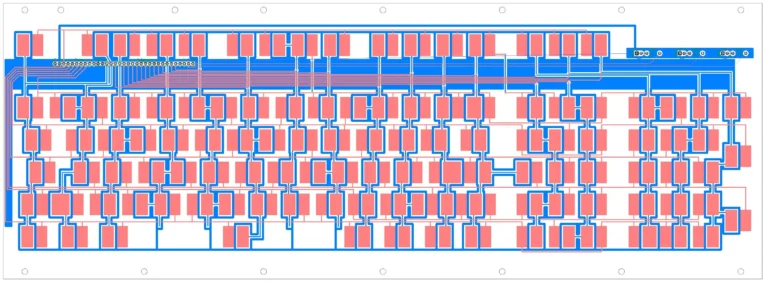
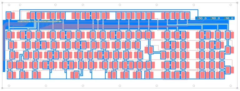
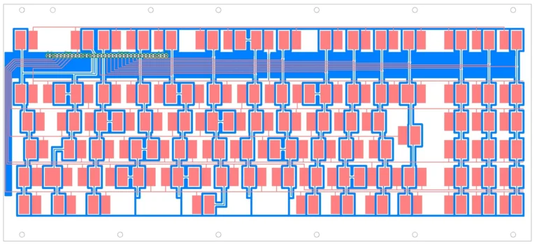
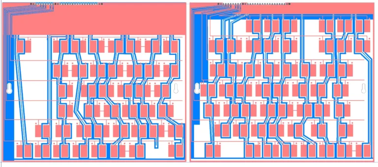
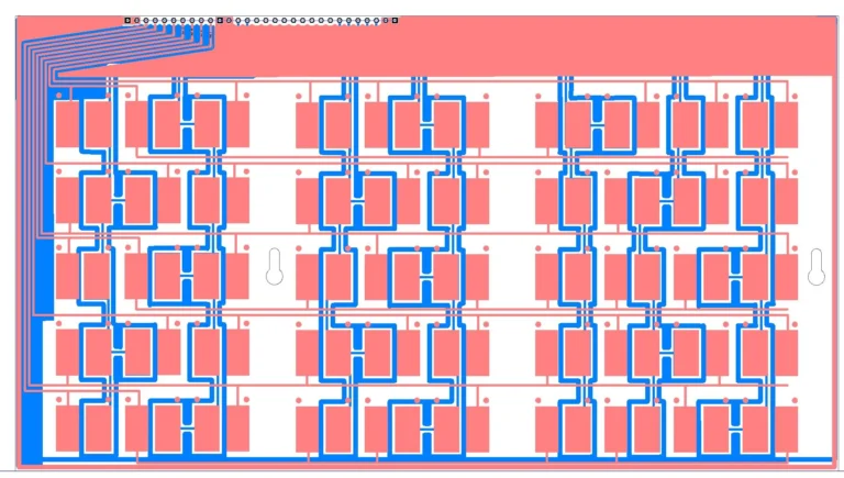
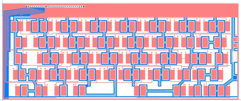
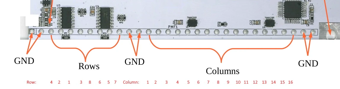
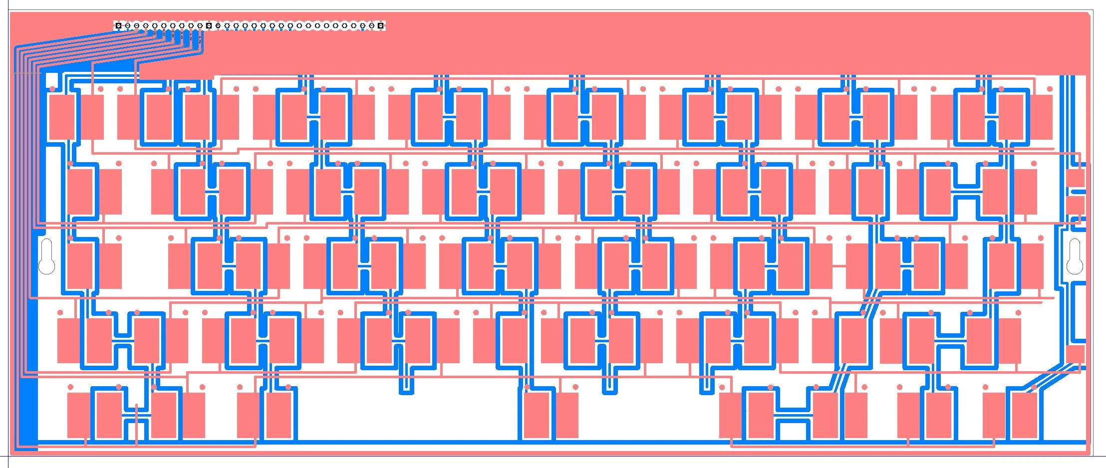
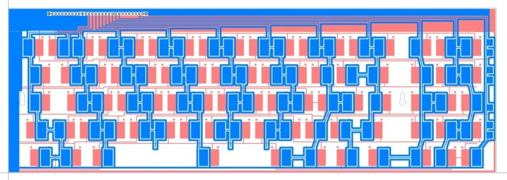
| Entire row or column of keys dead | Solder joint on ribbon cable needs touchup | Identify the affected trace in the PCB matrix diagram. Add solder to the corresponding through-hole on the controller side. See Section 4.4. |
4.1 Individual Keys Not Working
⚠️ Do not reinstall the same keycap over and over without adjusting the spring. That doesn’t fix anything.
Most key issues are spring-related. Follow this sequence:
- Remove the keycap
- Check that the flipper moves freely — nudge with tweezers if stuck
- Reseat the spring: twist off counterclockwise, reinstall straight down at 12 o’clock position, ~1mm from barrel edge, pressed firmly onto nub
- Try the spring upside down
- Replace the spring with a known good one (if you don’t have the first aid kit) or a spare from first aid kit
- Try a different keycap in that position (rare cap defects exist)
- Press the key 20–30 times after reinstalling to break it in
- If none of the above works → check for debris (see Section 4.5)
4.2 Large Keys (2U+) Getting Stuck — The Wiggle Method
Only for keys 2U and larger. Do not use on keys smaller than 2U.
- Pinch the key’s outer stem between thumb and forefinger, squeeze deeply
- Wiggle side to side 20–30 times
- Wiggle the key post (stabilizer insert pole) 10 times in the left-right direction
- Burnish the back of the stem — run your fingernail along the back side and angled portion
- Reinstall and test with 10–20 presses
- Repeat if improving but not fixed
- If the two “wings” of the stem are too close together, gently spread them ~1mm apart
⚠️ Don’t use the wiggle method on 2U vertical or 1.5U keys’ stems — they’ll snap. It’s OK for 2U’s posts though.
Additional fixes:
- Keep stabilizer insert 0.5–1mm above barrel top (especially shift keys)
- Try a horizontal (white) insert instead of vertical for 2U vertical keys
- If key is too loose: gently widen the stem
4.3 Keyboard Not Detected
| Symptom | Fix |
|---|---|
| “ATMEGA32 DFU” in Device Manager | Reflash firmware — see Section 6 |
| “Unknown USB device” error | Short the PROG pads and reflash firmware — see Section 6.6 |
| Nothing at all when plugged in | Check USB-C connection at controller end — try flipping the cable 180°. Try another port and another computer. If the keyboard is not detected – check that the USB cable is plugged in fully on the controller end of the USB cable as well. Realign the controller’s silver squares exactly with the bottom inner assembly ears |
| Works outside case, not inside | Ribbon cable contacting case bottom — add insulating tape (mostly an issue for ultra compact cases) |
Requirement for emailing me if a key does not work: You must attach screenshots of the signal level monitor after having pressed and held for three seconds each key (ok to press many keys at once to save time).
Controller alignment check:
- Remove both controller screws
- Lift controller away from bottom inner assembly
- Plug in USB — does it appear in Device Manager now?
- If yes: realign so the silver ground squares line up perfectly with the tabs
- Tighten screws while holding controller in position
4.4 Entire Row/Column Dead
This indicates a ribbon cable solder joint needs touching up.
- Open the pandrew utility / Leyden Jar diagnostic tool
- Switch to matrix view to identify which row/column is dead
- The matrix rows/columns don’t correspond to physical key rows — follow the PCB traces
- Find the trace: see your specific keyboard’s capacitive PCB trace diagram by clicking the below PCB image to open a gallery.
- Add solder: Unscrew the 2 controller screws, gently bend controller back, add solder to the affected through-hole from the component side. Also add to the capacitive PCB end of the same ribbon wire.
- No need to open the inner assembly for this fix
- If the Right ctrl on F62 or the right arrow key on F77 is not registering, column 16 needs to be retouched.






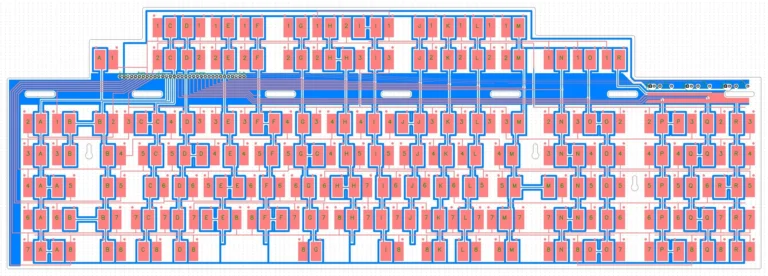

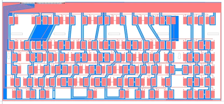
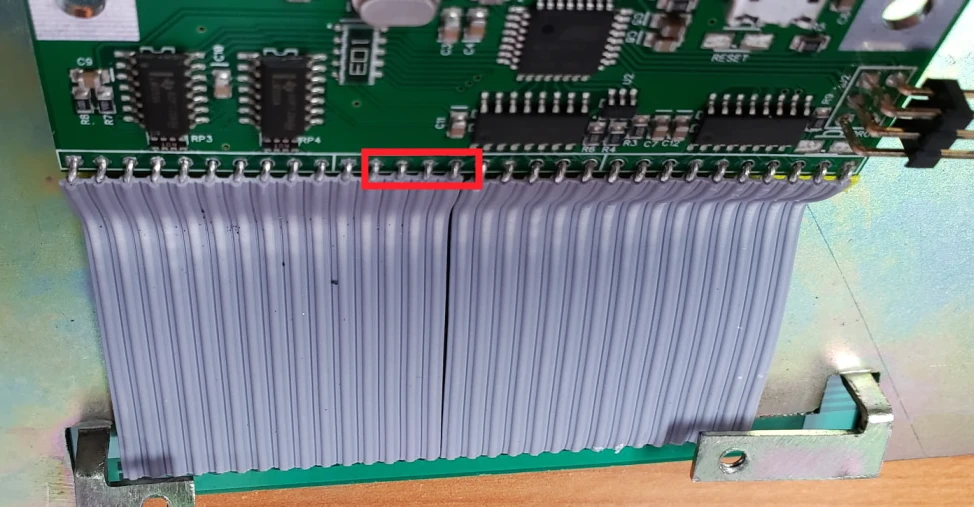
If values read “0”: Possible short to ground. Add insulating tape (Kapton/electrical) to bottom of controller where ribbon cables sit. Check for solder bridges. For ultra-compact cases: the ribbon cable may break through the Kapton tape and touch the case bottom. Push the ribbon cable end of the controller 1-2mm closer to the bottom inner assembly.
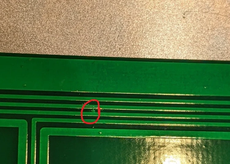
If two keys trigger from one press: Solder bridge connecting two traces — find and remove the bridge material. Bridged traces: Use an X-Acto or craft knife to very carefully cut any solder bridge on the PCB without cutting other traces.
4.5 Double Presses / Transposed Keys
In order of likelihood:
- Spring not seated properly — reseat per Section 3.4
- Spring not pressed fully onto flipper nub
- Spring end not at 12 o’clock
- Spring damaged — replace it
- Controller ground screws loose — tighten the 2 screws
- Another fix: slightly loosen the 4 screws inside the keyboard that attach the F104/FSSK/F122 inner assembly to the top case.
- Debris on PCB — try compressed air first, then:
- Remove nearby keys
- Tilt keyboard in different directions while moving springs
- Last resort: open inner assembly, wipe PCB with dry lint-free cloth
- Capacitive PCB shifted — when keyboard is open, ensure PCB sits fully down on the bottom inner assembly post
Quick debris test: Press and hold a key for 2 seconds, release 1 second, press again. Repeat 20 times. Consistent values = fine. Wildly varying values (130, 150, 168, etc.) = debris.
4.6 Random Disconnects
Check these in order:
- Don’t use a USB hub, KVM switch, or extension cable
- Try a USB 2.0 port directly on the motherboard
- Try a different cable
- Try on another computer
- Intel chipset USB power issue? Updating chipset drivers, BIOS firmware, or trying a different motherboard may resolve
- Check the cable’s strain relief; squeeze the controller’s USB-C connector slightly for a tighter connection; flip the USB-C plug 180 degrees and plug back in.
4.7 Using the Signal Level Monitor
⚠️ Important downloads to diagnose and flash firmware:
- xwhatsit controller (F50, F62, F77, FSSK, F104): download the pandrew utility
- Leyden Jar controller (F122, B104, B122): download the Leyden Jar diagnostic tool
⚠️ Never use the Key Press Monitor in these tools — it doesn’t work correctly for Model F diagnostics.
⚠️ Close pandrew/Leyden Jar tools before using Vial. Don’t have both diagnostic tools open together.


If a key registers an insufficient increase in value when pressed, try removing the keycap so that the spring has free movement. Without disconnecting the spring from the flipper, physically move the spring end to the top of the barrel so that the flipper lifts away from the large capacitive PCB underneath all the barrels; the value should decrease to be unpressed (red). Then let go of the flipper so it falls naturally; the value should be green (pressed). If it works without the keycap installed, the spring probably has to be reseated or replaced following the earlier-noted adjustment steps.
How to read pandrew:
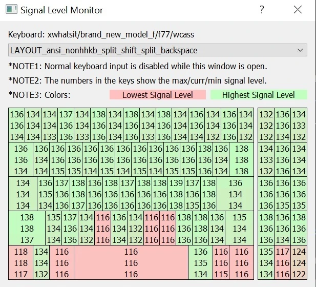
- In the pandrew utility, click Signal Level Monitor.
- Three numbers per key: highest, current, lowest
- Press and hold each key for several seconds — a quick press won’t register
- Unpressed: red, value ~110–125
- Pressed: should turn green, value 150+ (ideally 155–175+)
- Red when pressed = problem with spring installation or debris

How to read Leyden Jar:
- In the Leyden Jar diagnostic tool, click Refresh, then click Level Monitor. You must click the tool’s refresh button before the keyboard will appear. If you unplug the keyboard and plug it back in, you must click refresh again before anything will work.
- Three numbers per key: highest, current, lowest
- Press and hold each key for several seconds — a quick press won’t register
- Unpressed: black, value ~370-395
- Pressed: should turn blue, value high 380s+
- Black when pressed = problem with spring installation or debris
- Light blue when pressed = lower strength but ok (those that actuate within 10 values of the reference calibration level for that bin)
Note typical pressed and unpressed values are different for Beam Spring keyboards. It is normal for flipper capacitance to vary; this does not indicate a problem as long as it meets the reference level when pressed.
Mac note: First launch will be blocked. Go to System Settings → Security and Privacy → “Open Anyway” at the bottom.
🎬 Video — Signal Level Monitor

Signal Level Monitor: How to use the pandrew/Leyden Jar diagnostic utility — reading the three-number display (high/current/low), what green vs red means, pressed values to look for (155-175+), and how to diagnose springs vs debris vs. solder issues.
⚠️ If the signal level monitor shows you that just one or a few keys don’t work, now you understand why you don’t need to send an email for help because the electronics work just fine. From far away I can’t help make the required physical setup adjustments (remove and reseat a spring and keycap, etc.). The other sections in the manual describe what to do.
5. Solenoid Installation (optional)
⚠️ Read all warnings before starting. It’s easy to permanently damage the solenoid and driver.
Critical Safety Rules
- Match the square pad to the square pin (VCC to VCC) on both controller and solenoid driver. Wrong orientation = destroyed hardware.
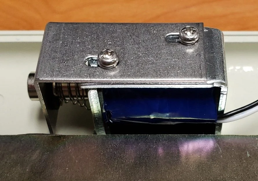
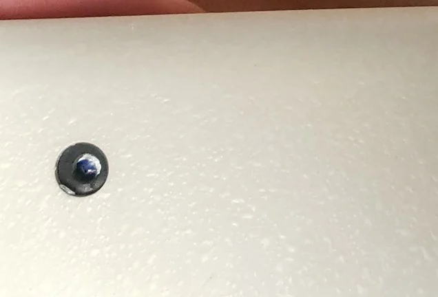
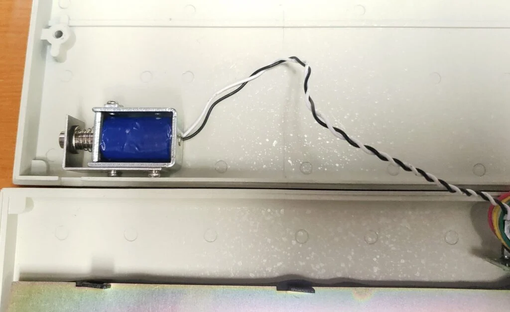
- Don’t overtighten the L-bracket screw — it can puncture the solenoid’s blue tape, destroying it
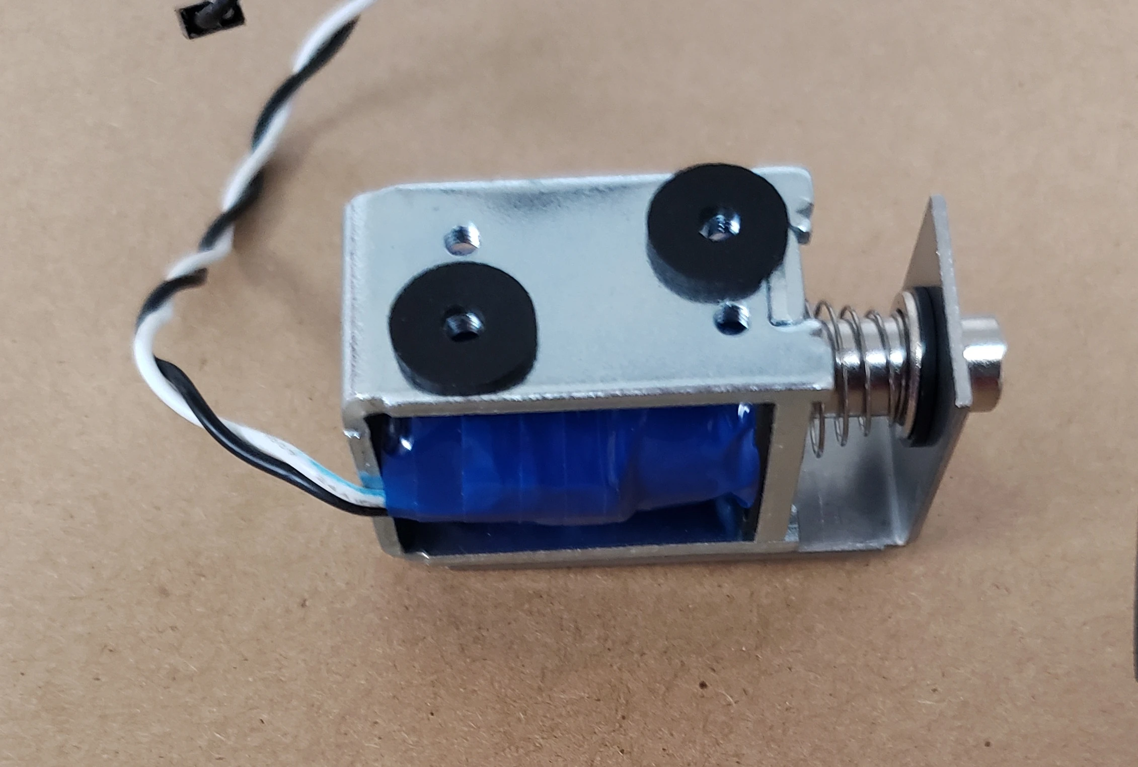
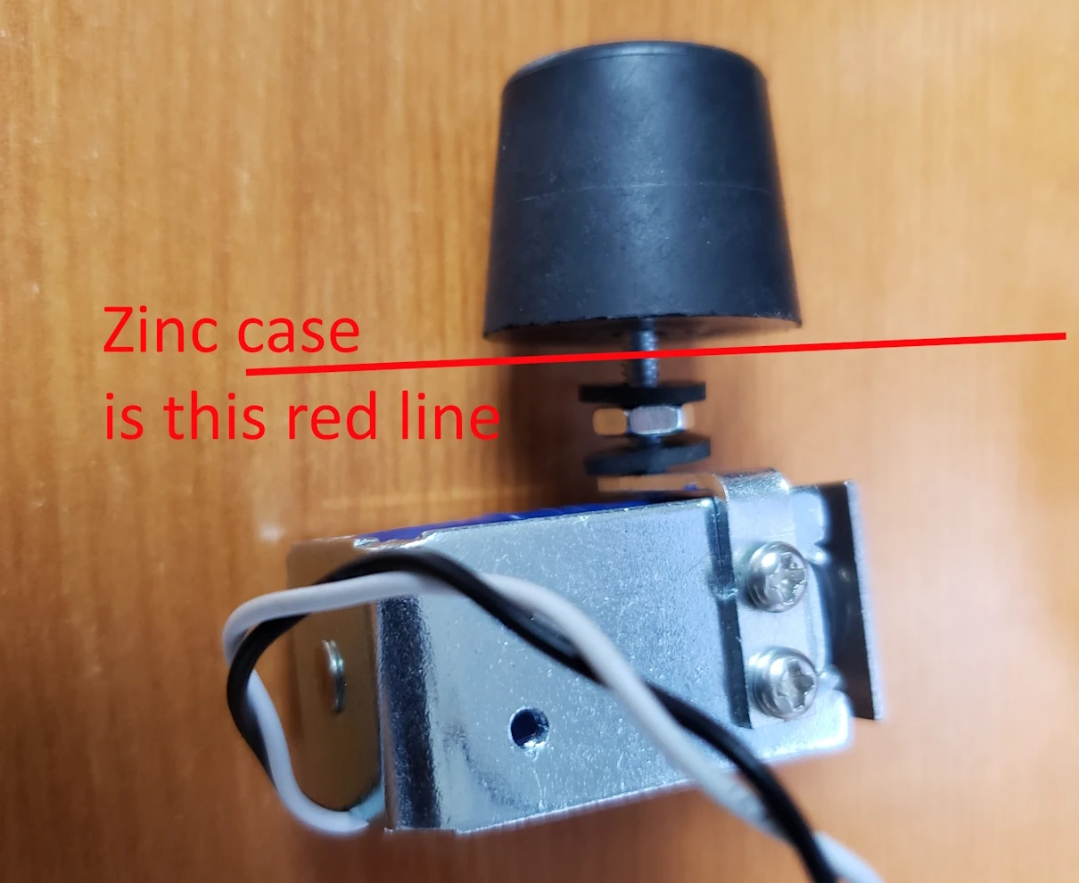
- Install rubber spacers between solenoid and mounting surface
- Push cable connectors fully in on both ends

What You Need (both available in the shop)
- Solenoid (sold separately)
- Solenoid driver (sold separately)
Toggle Solenoid On/Off
Fn + Spacebar + T
(Fn key location varies — see the Testing Keys area of Section 3.6 or check Vial to see which key is MO(1))
Adjusting the Solenoid
- Loosen the 2 screws on the solenoid body, slide the strike bar outward for maximum throw
- Zinc cases: maximum throw recommended
- Aluminum cases (M-style): shorter throw recommended (sound and feeling transmit more easily)
Installation by Case Type
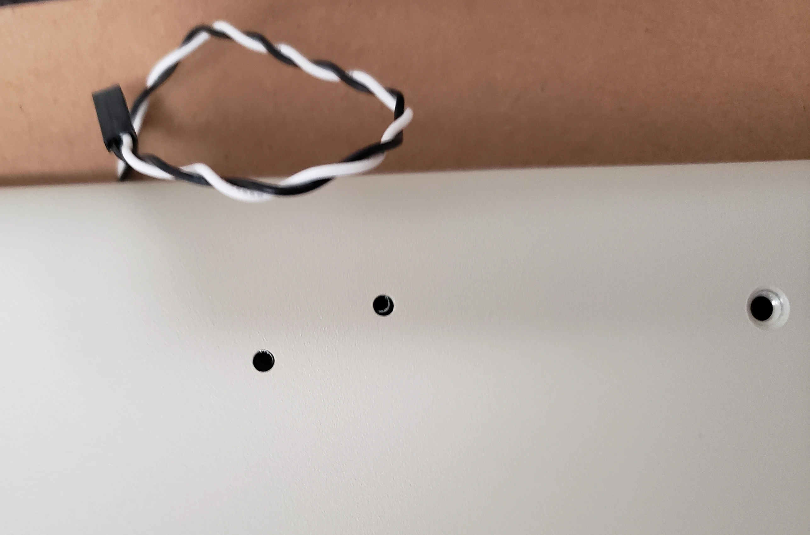
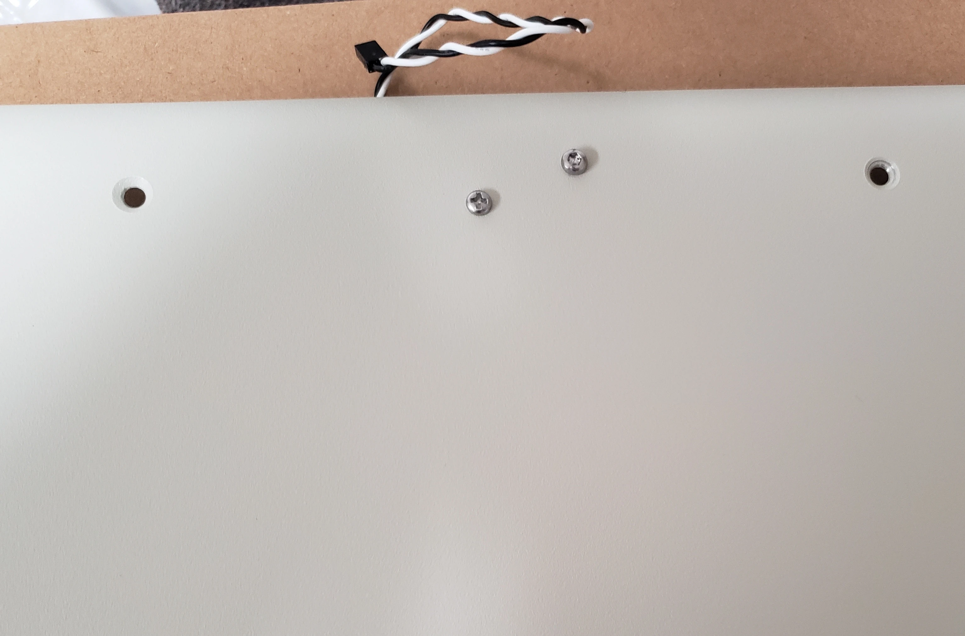
M-Style Cases (F104, FSSK, Beam Spring)
- Driver attaches to post on top case with 1/4″ 6-32 screw (dedicated mounting point)
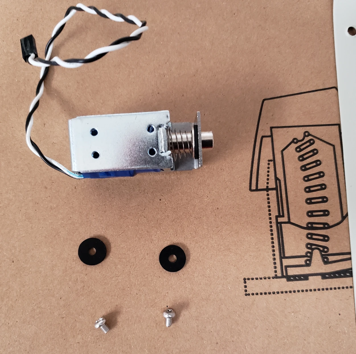
- Solenoid attaches to bottom case with 2 small M3×3mm screws
- Place rubber spacers between solenoid and case before attaching
- L-bracket not needed


Classic Cases (F62, F77)
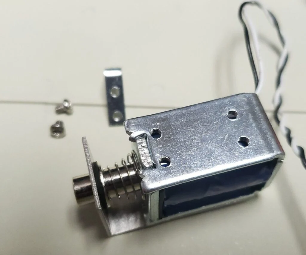
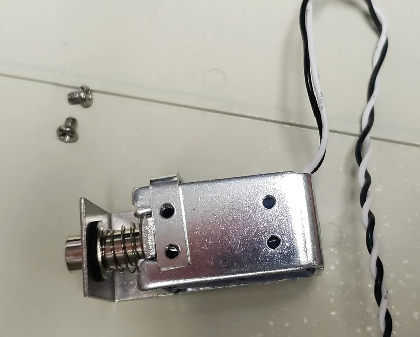
- Use the included L-bracket
- Bottom of solenoid driver PCB must face away from unpainted metal plate (add tape to PCB through-hole pins if needed)
- Be extra careful with 1-inch tall screw-on bumpers — the screw can reach the blue tape
- Consider using or ordering 3D printed solenoid holders for Classic F62/F77 cases or compact cases, as the solenoid may be too big or the medium threaded bumpers (8-32) will not work with the L bracket (6-32).


If Solenoid Doesn’t Work
- Verify firmware supports solenoid (reflash from official zip if needed)
- Erase EEPROM: Fn + Spacebar + E
- Move the plunger cylinder by hand a few times
- Check that the moveable bracket isn’t touching the cylinder
- Verify cable is fully seated on both ends
- Check square-to-square pin orientation
- Try moving the adjustable-length L bracket inwards so it is only half extended (possible issue with your USB port supplying enough power).
Any solenoid issue (not keeping up with keypresses, etc.) is most likely due to setup and your computer hardware, not due to an issue or limitation of the solenoid. Did you extend the solenoid L bracket so it is at least 50% extended? It may be related to an underpowered or failing USB port on your computer (laptop, KVM switch, USB hub, etc.). These keyboards place high demands on computers and a bad or loose USB port may not work properly, even if it works fine with other devices on the same port.
The default dwell time should not be changed as it may cause unexpected operation. The default settings work with hundreds of fast solenoid actuations during normal typing on a properly working USB port.
Advanced solenoid configuration – only if using original IBM keyboards
Due to factory default QMK settings, the solenoid will only be under full power if the dwell time is set properly. If you are using any of my files, this is done automatically. However, if you use the old pre-Vial QMK Configurator web site to make your firmware (nowadays only needed for the pandrew controllers for original IBM keyboards which haven’t been updated to Vial), program this into your own keyboard, drag the Any key to the key and layer you want (recommend layer 2), and then type in HPT_TOG to toggle, HPT_DWLI to increase the dwell time 1ms, or HPT_DWLD to decrease it. Each key has to be in its own box of course. Hold down the keys Fn+Spacebar++= (the + = key next to backspace) which has been preprogrammed to increase the Solenoid dwell time by 1 ms. Press it 20 to 25 more times to get it to the minimum required amount for full power. Recommended customization:
Fn+Spacebar+T–>Toggle the Solenoid On/Off (the solenoid is always on by default; pressing this one time will make a solenoid not work)
Fn+Spacebar+ -_ Decrease Solenoid dwell time HPT_DWLD
Fn+Spacebar+ -+ Increase Solenoid dwell time HPT_DWLD
Consult QMK GUI documentation for further details as this is beyond the scope of the new Model F keyboards.
🎬 Video — Solenoid Installation

Solenoid installation: Wiring the driver (match square pads for VCC!), mounting in F62/F77 zinc cases vs M-style cases, adjusting throw distance, and critical safety warnings about overtightening and blue tape puncture.
6. Firmware & Key Remapping
6.1 Using Vial (No Flashing Required)
Most keyboards ship with Vial firmware pre-installed (except some older F62/F77 stock; if you can’t open the keyboard with Vial you must flash the latest firmware).
- Go to vial.rocks in Chrome, Edge, or Opera
- Or download the Vial desktop app
- Plug in keyboard
- Click to connect
⚠️ Close pandrew/Leyden Jar utilities before opening Vial.
Note: Via ≠ Vial. Only Vial works with these keyboards.



🎬 Video — Vial Configuration
Vial key remapping: How to use the Vial web configurator (vial.rocks) to set up homerow mods, create custom layers, configure combo keys, and program macros. No firmware flashing needed.
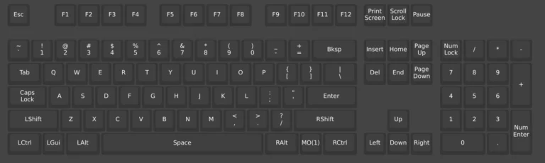
Default Vial configuration for F104 ANSI: Layers 0, 1, and 2


6.2 Flashing xwhatsit firmware — Windows
Prerequisites:
- Download ploxiln’s latest “newfxx_vial” release which includes firmware and the pandrew utility
- Extract all contents of the zip file
- Install driver (xwhatsit controllers only)
- Determine which bat file to double click:
The vial keymaps in keyboards/xwhatsit/brand_new_model_f/*/wcass/keymaps/ have labels/modifiers in their filenames with the following meanings:
- base is either ‘ansi’ or ‘iso’:
- ansi uses an ANSI Enter, and non-split left shift
- iso uses an ISO Enter, and a split left shift
- fn / hhshift / hhkb:
- fn means: split right shift (HHKB-style), with rightmost 1U key being mapped to Fn
- hhshift means: as above, but also Caps Lock and Left Ctrl are swapped relative to ANSI
- hhkb means: as above, but “full HHKB” (backspace is moved down a row to replace 1.5U backslash, original backspace is split)
- nlock / simulock:
- nlock means: enables the Num Lock layer 1 selection feature
- simulock means: “simulated” Num Lock (used on F77 only)
- optN: for F77, refers to the right-side block layout options
Steps:
- Plug in keyboard
- Open ploxiln’s pandrew utility → click Enter Bootloader
- Install ATmega driver if Windows shows exclamation mark in Device Manager


After completing the above steps, double-click the .bat file for your keyboard model (in the zip root, not in subfolders)
Never flash .hex files directly. Only use the provided bat files.
Windows 11 note: ATmega32U2 may not be recognized. Try: disable Memory Integrity (Windows Security → Core isolation), reinstall USB drivers, or adjust power management. Works fine for me without doing any of that.
6.3 Flashing Firmware — Mac and Linux
You can flash the firmware you built along with a keymap selected from keyboards/xwhatsit/brand_new_model_f/$MODEL/wcass/keymaps/$MODEL-* using the script flash-util/flash_vial_xwhatsit.sh.
- install “dfu-programmer”
- Debian,Ubuntu,etc: “sudo apt install dfu-programmer”
- Arch Linux: “sudo pacman -S dfu-programmer”
- macOS: “brew install dfu-programmer” or download from https://github.com/ploxiln/vial-qmk/releases
Determine which files to flash (see above notes in the Windows section).
Run the script and specify both the firmware and the keymap hex files:
./flash-util/flash_vial_xwhatsit.sh xwhatsit_brand_new_model_f_XXX.hex
          keyboards/xwhatsit/brand_new_model_f/$MODEL/wcass/keymaps/$MODEL-XXX.hex
On Linux you’ll probably have to run it with “sudo” (but not on macOS).
You’ll have to put the keyboard controller into “bootloader mode”, there are a few different ways:
- Run the pandrew-util, and click the “Enter Bootloader” button
- Run Vial, and go to Security > “Reboot to bootloader”
- Press the key on your keyboard mapped to the “RESET” function (modelfkeyboards.com default is Fn+space+R)
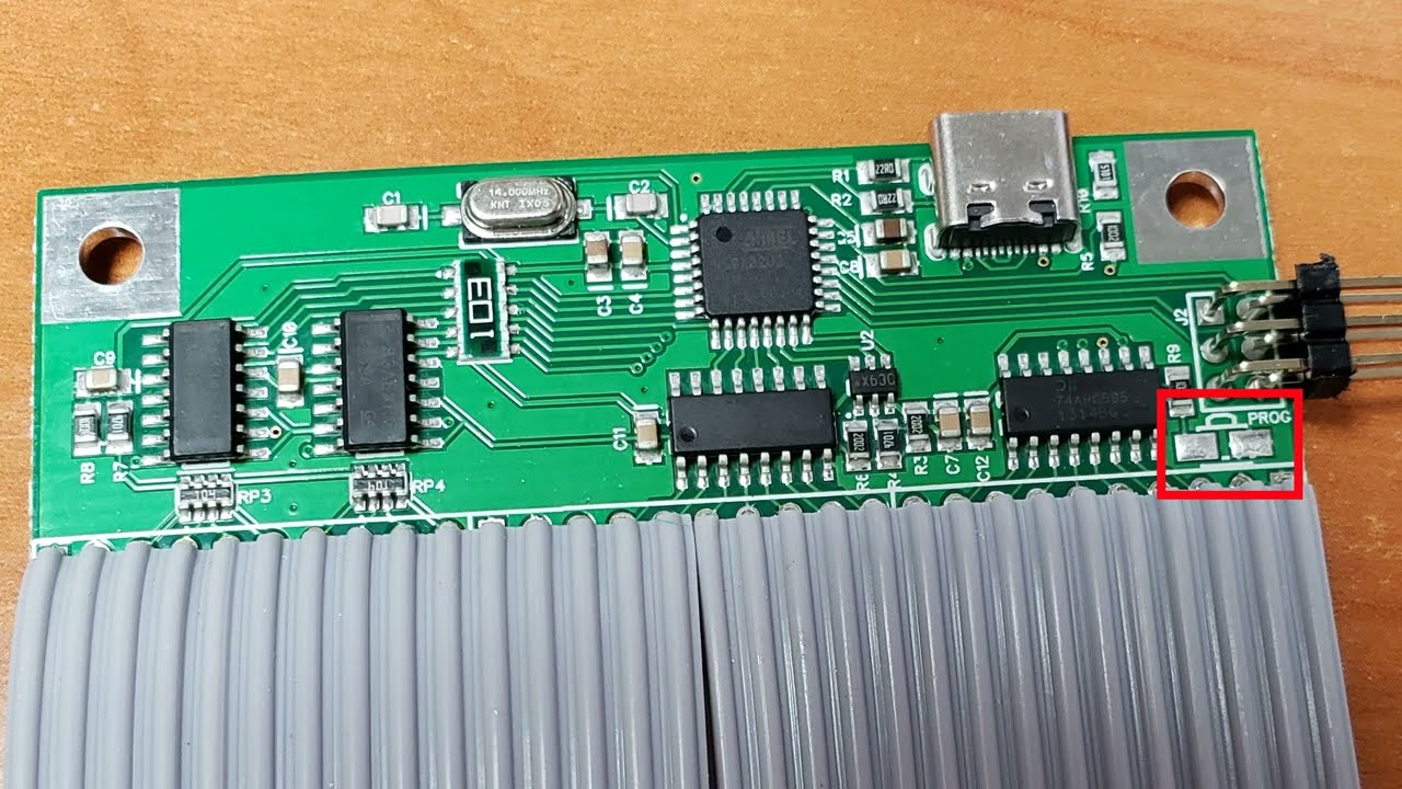
- Physically short the two pads marked “PROG” on the controller while plugging the USB cable into the host PC
If you have a split ergonomic model, each half is seen by the host computer as a discrete keyboard, and you will need to flash each half separately. The two firmwares for the two halves are suffixed with “left” / “right” or _l / _r.
macOS Tahoe (26) note: Can’t Control-click → Open anymore. Launch app → click Done on security popup → System Settings → Privacy & Security → scroll down → “Open Anyway”.
Credits: Latest update of xwhatsit firmware and the written guides on this page credit to ploxiln, based on prior work from NathanA, pandrew, and xwhatsit.
6.4 Flashing Firmware — Leyden Jar Controllers (F122, B104, B122)
- Open Leyden Jar diagnostic tool
- Click Refresh Device List
- Click Enter Bootloader
- An empty drive named “RPI-RP2” appears
- Copy the
.uf2firmware file to this drive - Keyboard reboots automatically
⚠️ You must click Refresh before Enter Bootloader, or it won’t work.
For “all pads” layouts (split/unsplit keys): flash the generic firmware first (e.g., leyden_jar_f122_vial.uf2), then use Vial to adjust.
To compile the Leyden Jar diagnostic tool from source in Windows, clone the git repo from within Visual Studio 2022 to ensure submodules get cloned, then hit Build All.
Filename examples to help you determine which Leyden Jar file to flash:
| Name | Type | Right Shift | Ctrl/Caps Position |
| leyden_jar_f122_vial-iso-hhkb-split-rshift-split-backspace-hhkb-ctrl-caps.uf2 | ISO | HHKB-style split (1.75U+1U) | Regular |
| leyden_jar_f122_vial-iso-hhkb-split-rshift-split-backspace.uf2 | ISO | HHKB-style split (1.75U+1U) | HHKB (Ctrl to the left of “A”) |
| leyden_jar_f122_vial-iso-hhkb-split-rshift-hhkb-ctrl-caps.uf2 | ISO | HHKB-style split (1.75U+1U) | Regular |
| leyden_jar_f122_vial-iso-hhkb-split-rshift.uf2 | ISO | HHKB-style split (1.75U+1U) | HHKB (Ctrl to the left of “A”) |
| leyden_jar_f122_vial-iso.uf2 | ISO | Regular 2.75U | Regular |
| leyden_jar_f122_vial-ansi-hhkb-split-rshift-split-backspace-hhkb-ctrl-caps.uf2 | ANSI | HHKB-style split (1.75U+1U) | Regular |
| leyden_jar_f122_vial-ansi-hhkb-split-rshift-split-backspace.uf2 | ANSI | HHKB-style split (1.75U+1U) | HHKB (Ctrl to the left of “A”) |
| leyden_jar_f122_vial-ansi-hhkb-split-rshift-hhkb-ctrl-caps.uf2 | ANSI | HHKB-style split (1.75U+1U) | Regular |
| leyden_jar_f122_vial-ansi-hhkb-split-rshift.uf2 | ANSI | HHKB-style split (1.75U+1U) | HHKB (Ctrl to the left of “A”) |
| leyden_jar_f122_vial-ansi.uf2 | ANSI | Regular 2.75U | Regular |
| leyden_jar_f122_vial.uf2 | Special “All Pads by Default” | ||
6.5 Entering Bootloader When Nothing Works
If Enter Bootloader button and Fn+Space+R both fail:
- This is useful if your keyboard suddenly won’t start or won’t show up as a device on your computer.
- Unplug the USB cable
- Unscrew the 2 controller screws to access the component side. Be careful bending back the controller ribbon cable (always hold the ribbon cable in place and bend in the middle, already bent area of the ribbon cable; if you bend back the ribbon cable at either end you will wear down the cable and the keyboard will eventually stop operating properly).
- For xwhatsit: locate the PROG pads (not the Reset pads — they’re on opposite sides)
- Use sharp metal tweezers (not a screwdriver — surface oxidation prevents contact)
- Apply firm, constant pressure to short the pads
- While shorted, plug in the USB cable
- Within a split second, remove the tweezers
- Listen for the Windows USB plug-in sound
- May take 2–3 attempts
- Shorting it after the keyboard is plugged in or leaving it shorted will not do anything.
- For Leyden Jar: locate the Boot pads (can be found on either side of the PCB). Double tap the boot button until you see RPI-RP2 in your Explorer (important note: must do this very fast; may take several tries).
6.6 Additional Right-Side Block Layouts for F77 (if you ordered Blocks 3, 4, 5,or 6)
- Flash the appropriate
.batfile (nlock or simulock variant) - Open vial.rocks
- Layout tab: set split right shift to “No Split” if you have ANSI/ISO, or leave it unchanged if you have HHKB-style split right shift
- Keymap tab: change
MO(2)on right shift toRShift
Flash the firmware whose bat file name contains one of the two options below, depending on your preference.
nlock: enables the Num Lock based layer 1 selection feature; matches your computer’s num lock state (recommended option)
simulock: simulated Num Lock trigger without actually changing host Num Lock status. This was an earlier solution before the advent of host Num Lock based layer switching, but is preserved because some users may find this version preferable.
🎬 Video — Firmware Flashing (xwhatsit)
Firmware flashing (xwhatsit): Installing Atmel Flip, clicking Enter Bootloader in the pandrew utility, running the .bat/.sh flash scripts, and what to do if you see “waiting for keyboard.” Includes driver installation for Windows. Please note that the driver installation has changed and Atmel Flip is no longer compatible with the ploxiln files; please follow the above instructions for the driver installation before proceeding with the other steps in this video.
7. Opening the Keyboard / Changing Layouts
📹 Video guides: See the F104/F122/FSSK disassembly video and the F62/F77 disassembly video at the bottom of this section for visual walkthroughs.
⚠️ Always remove ALL keys before opening the inner assembly.
Opening
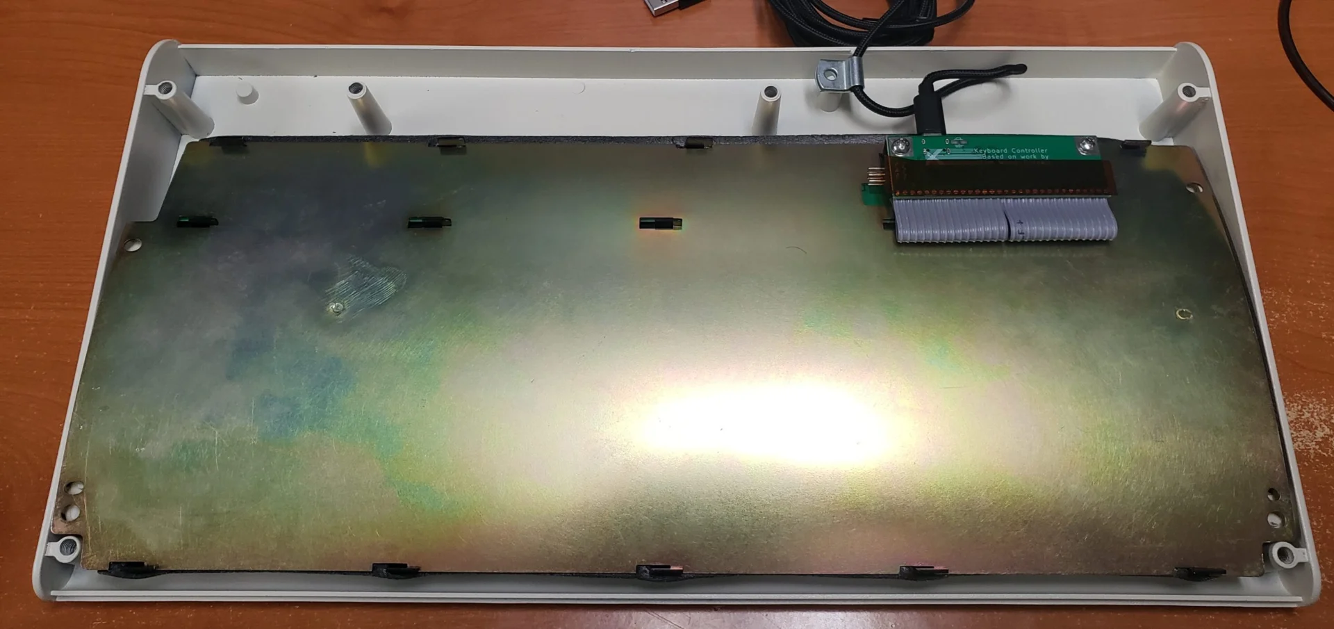
- Bend outward the locking tab (top right with the keyboard as oriented below) to clear the bottom inner assembly
- For M-style keyboards: lift the ribbon cable slightly higher so it is away from the tab hidden below it
- Use pliers to slide the tabs of the top inner assembly
Possible Layout Changes
- ISO ↔︎ ANSI
- Split/unsplit: backspace, left shift, right shift, enter, spacebar
- Split right shift to JIS-style (1U+1.75U) on ANSI/ISO — but not HHKB-style (1.75U+1U)
- You cannot switch between HHKB split right shift and standard without new parts (PCB, top inner assembly, inner foam, though this may change in the future)
Closing
- Keep keyboard upside down throughout
- F62/F77: bend larger tabs outward slightly before clamping
- Slide bottom tabs together until they can’t go further
- Use pliers (or C clamps for larger models) to press down and bend tabs inward
- Last tab (rightmost when upside down) is the locking tab — secure carefully
- F62/F77: place inner assembly on top case, add bottom case, screw together
- F104/FSSK/F122: screw in 4 screws attaching bottom inner assembly to top case
Case Wobble Fix
- Add a thin washer on the post inside the keyboard at the wobbling corner
- Or gently bend the case over your knee (be careful!)
- Or slightly loosen case screws where case should be lower, insert folded paper as shim

Switching Case Styles (F62/F77 only)
Remove inner assembly → swap to alternative bottom inner assembly plate → reassemble in new case.
🎬 Videos — Opening the Inner Assembly

Disassembly (large keyboards): How to open the F104, F122, and FSSK inner assemblies — bending the locking tab, using C-clamps, sliding tabs, and safely reassembling without damaging the ribbon cable.

Disassembly (small keyboards): Opening and closing the F62 and F77 inner assemblies — tab bending technique, plier placement, and how to change between compact and classic case styles.
8. Mods & Maintenance
8.1 Cleaning
- Unplug keyboard — always
- Keycaps and barrels: mild dish soap + lukewarm water. Ultrasonic cleaner works great.
- Air dry overnight with good airflow (fan + towel). Don’t reinstall until fully dry — water in crevices causes issues.
- Springs/flippers: only clean with dry cloth unless there’s visible residue
- Case: mild soap and water. Melamine sponge works but can remove paint.
- Controller: never get wet
- Liquid spill: disassemble immediately. Scrub every flipper and the PCB with mild dish soap + water. Air dry for a full day.
8.2 Sound Mods
Floss Mod
Dental floss wrapped around the spring to dampen sound. Can increase key weight slightly. If you use paracord instead, key weight will noticeably increase (good if you desire more weighting).
Grease Mod (Soft Touch)
Apply Synco Superlube inside the spring with a metal probe — just enough to dampen vibration. Same feel, same click, dramatically reduced spring ring.
Dab of Glue in Barrel
Place in the barrel at approximately the 7 o’clock position to reduce flipper return noise.
Pressing Springs Fully Down
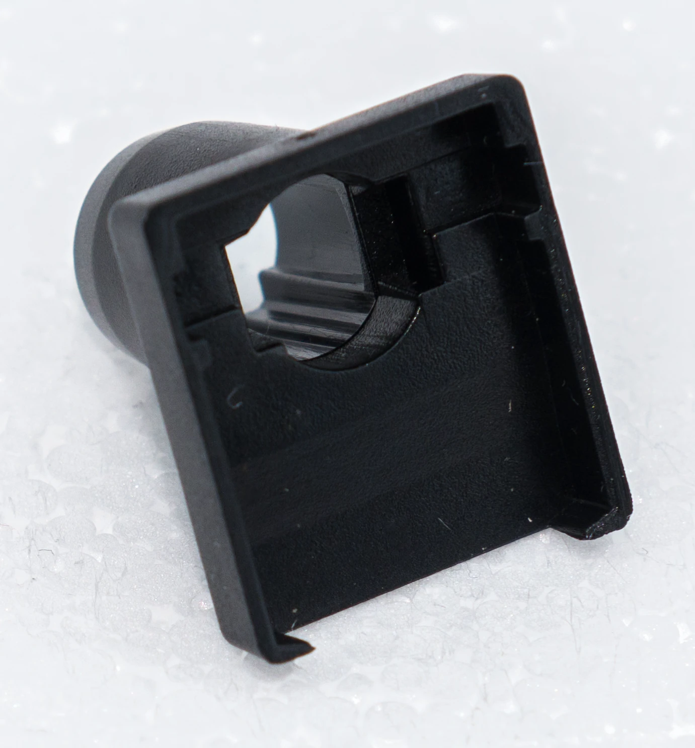
Reducing the 0.2–0.3mm gap between spring and flipper reduces ringing.
Case Dampening
Consider polyfill, Blu Tack, 5mm PE foam.
8.3 Trackpoint Mod
Add a Unicomp M13 trackpoint to your Model F. Photo gallery. Uses Unicomp GHB keys with trackpoint cutout.
8.4 Bluetooth Mod
8.5 Flush-Mount USB-C
For M-style cases: GitHub project
Additional Mod Resources
- darkcruix’s comprehensive Model F guide (Deskthority)
- Twst’s mod comparison videos
- 3D printed legs for split boards
9. Reference
9.1 Default Key Commands
Fn + Spacebar + Key:
| Key | Function |
|---|---|
| T | Toggle solenoid on/off |
| + = | Increase solenoid dwell time |
| – _ | Decrease solenoid dwell time |
| E | EEPROM reset (erases all settings) |
| R | Reset / enter bootloader |
| D | Debug mode |
| N | Toggle NKRO |
Fn + Key:
| Key | Function |
|---|---|
| Esc | Power |
| F1 | Brightness Down |
| F2 | Brightness Up |
| F6 | Media Stop |
| F7 | Media Previous |
| F8 | Media Play/Pause |
| F9 | Media Next |
| F10 | Mute |
| F11 | Volume Down |
| F12 | Volume Up |
| Print Screen | Eject |
9.2 NKRO
All Model F and Beam Spring boards have NKRO, but factory default setting is 6KRO (6-key rollover) for maximum compatibility.
To enable full NKRO: Go into Vial, assign MAGIC_TOGGLE_NKRO to the N key on Layer 2 (Fn + Spacebar + N). Already done on Leyden Jar firmware.
NKRO doesn’t persist after reboot? Known QMK/Vial bug on some hardware. Workaround: assign keycode 0x7C01 to a key, press it after each reboot.
NKRO caveats:
- Mac: can’t enter Recovery Mode or reset NVRAM with NKRO on
- Some UEFI/BIOS don’t support it
- Some programs handle NKRO inconsistently
9.3 QMK Solenoid Keycodes
| Keycode | Function |
|---|---|
HPT_ON | Haptic feedback on |
HPT_OFF | Haptic feedback off |
HPT_TOG | Toggle haptic on/off |
HPT_RST | Reset haptic config to default |
HPT_FBK | Toggle feedback on keypress / release / both |
HPT_BUZ | Toggle solenoid buzz |
HPT_DWLI | Increase solenoid dwell time |
HPT_DWLD | Decrease solenoid dwell time |
9.4 Controller Identification
| Controller | Used In | Firmware Tool | Device Manager Shows |
|---|---|---|---|
| xwhatsit | All other keyboards except below | pandrew utility | “Brand New Model F Keyboard” (QMK/Vial) or “ibm_capsense_util” (old xwhatsit FW) |
| Leyden Jar (RP2040) | F122, B104 R2, B122 | Leyden Jar diagnostic tool | “Model F Labs” |
| Original xwhatsit | IBM originals | xwhatsit utility | varies |
9.5 Downloads & Links
| Resource | Link |
|---|---|
| Vial (web) | vial.rocks |
| Vial (download) | get.vial.today |
| Latest xwhatsit firmware (ploxiln) | GitHub |
| Leyden Jar firmware | GitHub |
| Leyden Jar diagnostic tool | GitHub |
| YouTube channel | Brand New Model F Keyboards |
| NathanA xwhatsit firmware (old; superseded by ploxiln) | newfxx-firmware.nconx.com |
| Beta QMK Configurator (IBM originals only) | Link |
| Original 2014 xwhatsit firmware and installation guides (old) | Link |
| xwhatsit’s 2014 technical writeup for the controller | Link |
Manual Credit and terms: Credit for the design and most of the rewriting/reorganization of the manual go to a helpful Model F user. Everyone please email me for further specific content to add or rework if needed. The manual, like all other content, is provided AS IS and is subject to errors and omissions.